Chapter 8
RA83/84/85/93/94/95 Series
Trouble Shooting And On Board Servicing Operation
Manual
Y
○
1
N
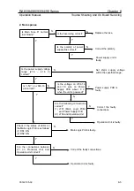
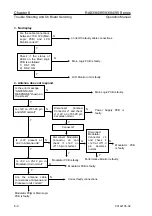
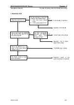
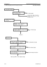
Is the motor power supply voltage
(12V) present on J4-5 and J4-4?
Y
Is the degree of motor brush
degradation within the allowance
(less than 6 mm)?
Internal wirings in the Antenna
unit or Power Supply in the
Processor unit is faulty.
N
Replace the motor brushes.
Antenna motor is faulty.
Y
Y
N
N
Y
Y
N
N
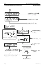
Is the HM pulse signal
on J3-1 (Modulator
PCB) normal?
3 msec
HM signal
1.2 msec
Azimuth signal
5 V
2.5 V
0 V
Normal Azi & HM signals on J1-7
5 V
0 V
10 ms
Is the HM pulse signal on J4-2
(Modulator PCB) normal?
The error message “HEADING
LINE ABNOTMAL” is shown
Is the Azi Pulse signal
present on J1-7 (Modulator
PCB) normal?
The error message
“AZIMUTH ABNORMAL”
is shown
Is the HM signal on J1-7 (Modulator
PCB) normal? (See waveform above)
Internal wirings in the
Antenna unit or Power
Supply in the Processor
unit is faulty.
Modulator PCB is faulty.
The photo-interrupter
is faulty.
Modulator PCB
is faulty.
Internal wirings in the Antenna unit or Power
Supply in the Processor unit is faulty.
Reed switch is faulty.
8-14
93142105-02

