Chapter 6 RA83/84/85/93/94/95 Series
Using The Menu
Operation Manual
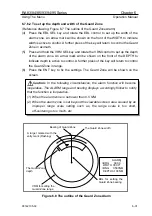
TEST
HDG 090.0°
TEST
SPD 12.0 KT
X
X
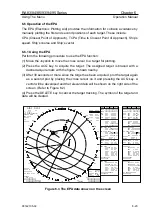
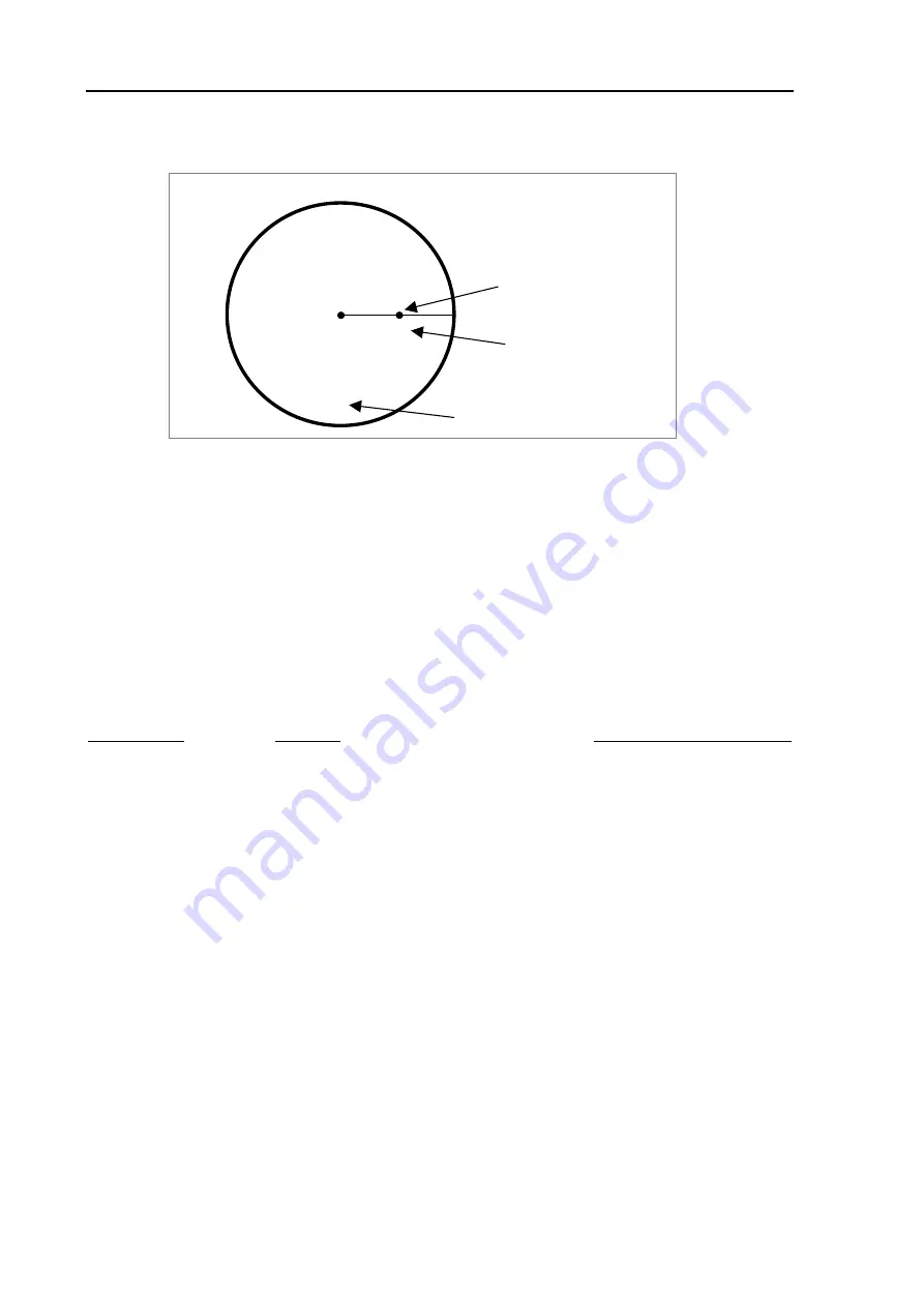
The ATA test mode sign
Test target ID letter
6 NM
Test target
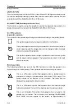
Figure 6.2 The ATA test mode display
(6) To perform the ATA test function, use the SYSTEM/BITE/ATA TEST menu.
6.5 MAINTENANCE MENU
This menu is protected from ordinary operation. To activate this function, press and
hold the Mode Key and turn the unit on.
6.5.1
ANTENNA
The following maintenance test items will be shown:
Items shown Meaning
Normal indication (range)
TUNING LEVEL
Tuning Level Indicator
10 to 20
TUNING VOLTAGE
Tuning Voltage Level Monitor
50 to 240
250V(HT)
250V monitor
100 to 180
MAG. CURRENT
Magnetron Current Monitor
5 to 240
P.M. RX
Performance Monitor Receiver Level
10 to 240
P.M. TX
Performance Monitor Transmitter Level
10 to 240
ANTENNA TYPE
1
ANTENNA MODE
Scanner Unit ID2
ID No. (See NOTE)
NOTE:
ID number varies according to the transmission power level as follows:
7: 6 kW, 0: 12 kW, 5: 25 kW
6-22
93142105-02

