RA83/84/85/93/94/95 Series
Chapter 6
Using The Menu
Operation Manual
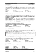
6.7.6.2 To set up the depth and width of the Guard Zone
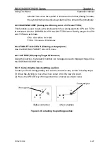
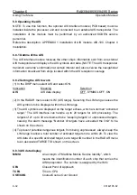
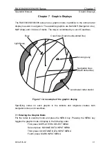
(Reference drawing: Figure 6.7 The outline of the Guard Zone Alarm)
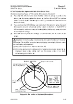
(4) Press the EBL SEL key and rotate the EBL control to set up the width of the
alarm zone. An arrow mark will be shown on the front of the WIDTH to indicate
width is active to control. A further press of the key will return to control the Guard
Zone in azimuth.
(5) Press and hold the VRM SEL key and rotate the VRM control to set up the depth
of the alarm zone. An arrow mark will be shown on the front of the DEPTH to
indicate depth is active to control. A further press of the key will return to control
the Guard Zone in range.
(6) Press the ENT key to fix the settings. The Guard Zone will be shown on the
screen.
Caution: In the following circumstances, the alarm function will become
inoperative. The ALARM range and bearing displays accordingly flicker to notify
that the function is inoperative.
(1) When the alarm zone is set lower than 0.5 NM.
(2) When the alarm zone is set beyond the viewable screen area caused by an
improper range scale setting such as, the range scale is too short,
off-centering is too much, etc.
The Guard Zone width
EBL for setting the
Guard Zone bearing
VRM for setting the
Guard Zone range
ALARM
>BRG 000.0
o
WIDTH
000.0
o
>RNG 0.500NM
DEPTH 0.100NM
Bearing of Guard Zone
The Guard Zone
depth
A target marked with the
entry mark (Flashing)
Figure 6.8 The outline of the Guard Zone Alarm
93142105-02
6-31

