


K134sm7e2
7-20
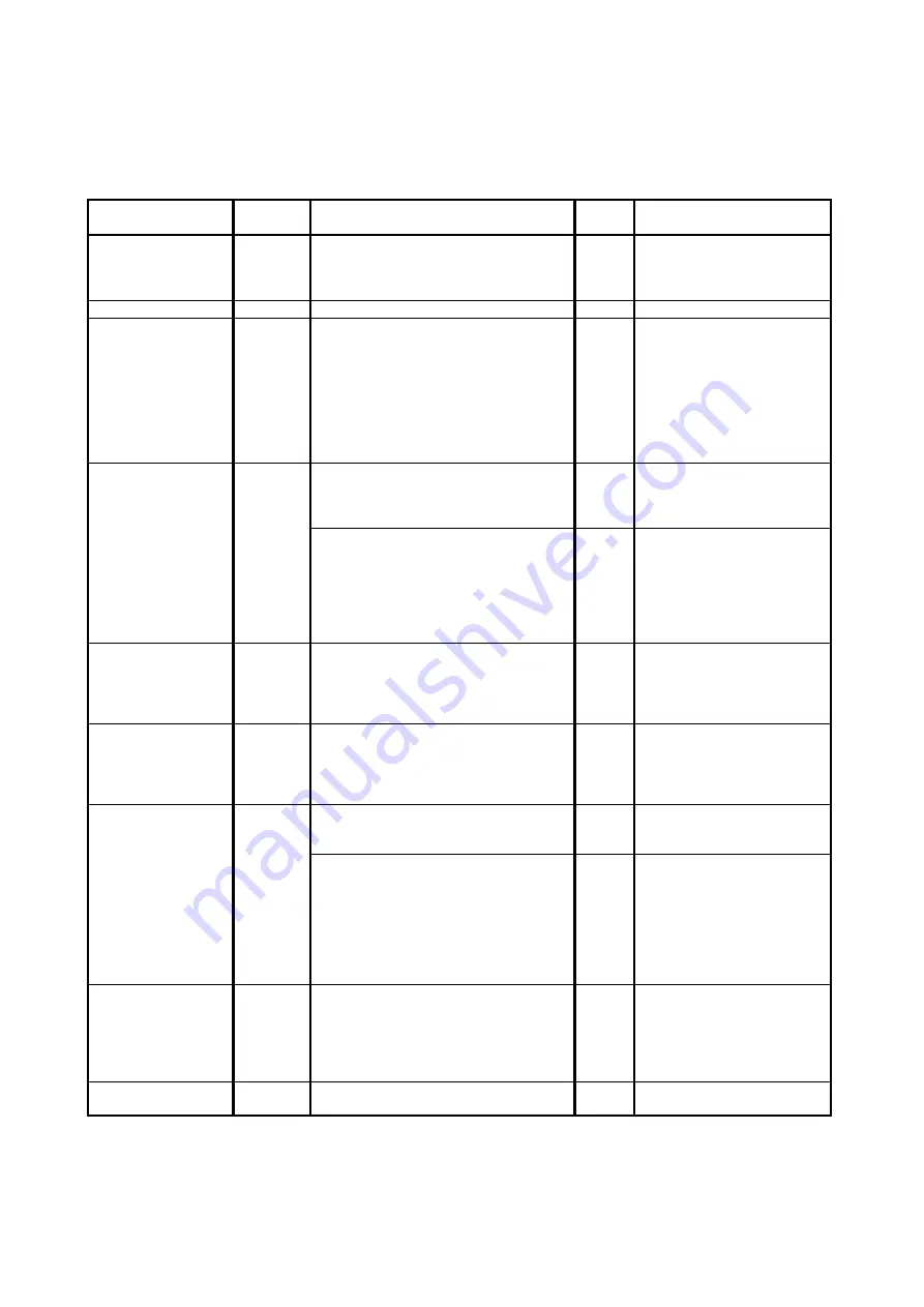
7. 2. 2 Countermeasures - Image Quality
7. 2. 2. 1 Halftone is too light
Check the following matters with the Pattern Print, pattern: #01_00 and pattern: #03_00.
If necessary use other Test Patterns.
Cause
Checking
order
Checking
Result
Treatment
1
Try to readjust each image creation
component according to [7.2.1 Basic
Image Adjustment]. Is the problem
fixed?
Yes
OK
LED Head
2
Is the Lens Array of LED Head dirty?
Yes
Clean it.
Paper
3
Can you fix the problem if you use a
newly unpacked paper?
Yes
1. If the paper was
humidified, instruct the
customer of the way store
the paper.
2. If the paper was not the
specified one, explain the
customer that some
image problem may
occur in that case.
Image Corona
4
Is the Image Corona dirty?
Yes
Clean each Corona Wire,
Grid Plate and housing, or
replace the Corona Wire if it
is too dirty.
Is the input voltage to the Image
Corona correct?
No
Readjust the input voltage
making reference to [4. 3. 2
Check & Adjustment of
Analog Voltage to the Image
Corona].
Or replace the HV Power
Supply PCB.
Eraser Lamp
5
Does the Eraser Lamp light properly?
No
1. Check the wire
connected to the Eraser
Lamp.
2. Check or replace the
Eraser Lamp.
Separation Lamp
6
Does the Separation Lamp light
properly?
No
1. Check the wire
connected to the
Separation Lamp.
2. Check or replace the
Separation Lamp.
Transfer Corona
7
Is the Transfer / Separation Corona
dirty?
Yes
Clean each Corona Wire
and housing, or replace the
Corona Wire if it is too dirty.
Is the input voltage to the Transfer
Corona correct?
No
Readjust the input voltage
making reference to
[4. 3. 3 Check &
Adjustment of Analog
Voltage to the Transfer
Corona].
Or replace the HV Power
Supply PCB.
Contact points of
Developer Bias
8
Is each Electrode Plate on the right of
the Developer Unit surely contacted to
the Electrode Plate on the machine
side?
No
Try to install the Developer
Unit so that they are
contacted each other.
And supply the conductive
grease to the Electrode
Plates.
HV Power Supply
PCB
9
Can you fix the problem if you replace
the HV Power Supply PCB?
Yes
OK
Summary of Contents for 7170K
Page 1: ...KIP 7170K Service Manual Version A...
Page 46: ...K134sm2e5 2 28 7 Press GUIDES 8 Press Help 9 Press Settings SETTINGS screen appears...
Page 76: ...K134sm2e6 2 58 31 Type 4 with keypad and then click OK on the bottom 32 Click OK on the bottom...
Page 108: ...K134sm4e1 4 4 120V model 230V model 8 7 10 11 12 15 14 13 9...
Page 189: ...K134sm5e4 5 36 64 Press GUIDES 65 Press Help...
Page 384: ...K134sm5eH 5 231 3 Remove both Covers 3 5 6 pulling their sides outward 5 6...
Page 395: ...K134sm5eH 5 242 6 Remove the Blower 9 BL3 BL4 moving as the following photos 9 9...
Page 502: ...K134sm6e1 6 15...
Page 563: ...K134Ksm8e2 8 4 4 Press GUIDES 5 Press Help...
Page 564: ...K134Ksm8e2 8 5 6 Press Setting to indicate SETTINGS page...
Page 594: ...K134Ksm8e2 8 35 2 Press All Items 3 Press Export...
Page 747: ...K134Ksm8e7 8 188 8 9 2 Operation in Error Mask 1 Press Error Mask...
Page 749: ...K134Ksm8e7 8 190 8 9 3 Operation in Jam Mask 1 Press Jam Mask...
Page 750: ...K134Ksm8e7 8 191 2 Select the desired target...
Page 754: ...K134Ksm8e7 8 195 8 11 2 Changing Counter Value 1 Press Total Count 2 Press Edit...
Page 756: ...K134Ksm8e7 8 197 5 Press Edit to enable new value 6 Close the following message pressing OK...
Page 777: ...K134Ksm8e7 8 218 8 19 Communication Reset NOTE This function is not used in the market...
Page 839: ...K134sm8e8 8 280 29 Double click on the row No 15 Stitch Setting 1...
Page 863: ...K134sm9e1 Chapter 9 Appendix...
Page 864: ...KIP 7170 Overall Circuit Diagram USA 120V_KCS...


