


K134sm4e3
4-39
2. Make a Test Print making reference to [8. 3 Pattern Print].
As the Negative Developer Bias is supplied to the Developer Roller during the Test Print, check
the voltage with the multi-meter.
The standard value of the Negative Developer Bias for each type of media is:
Plain paper
-180 +/-5V against the ground (-200 +/-5V : CND Model)
Tracing paper
-180 +/-5V against the ground (-200 +/-5V : CND Model)
Film
-180 +/-5V against the ground (-200 +/-5V : CND Model)
If the above values are not satisfied, go to the next step.
3. If the value (voltage) is -230 +/- 5V, Developer Bias may be automatically adjusted by Density
Compensation Process.
(As the CND model machine does not use “Density Compensation Process”, it is set as “OFF”.)
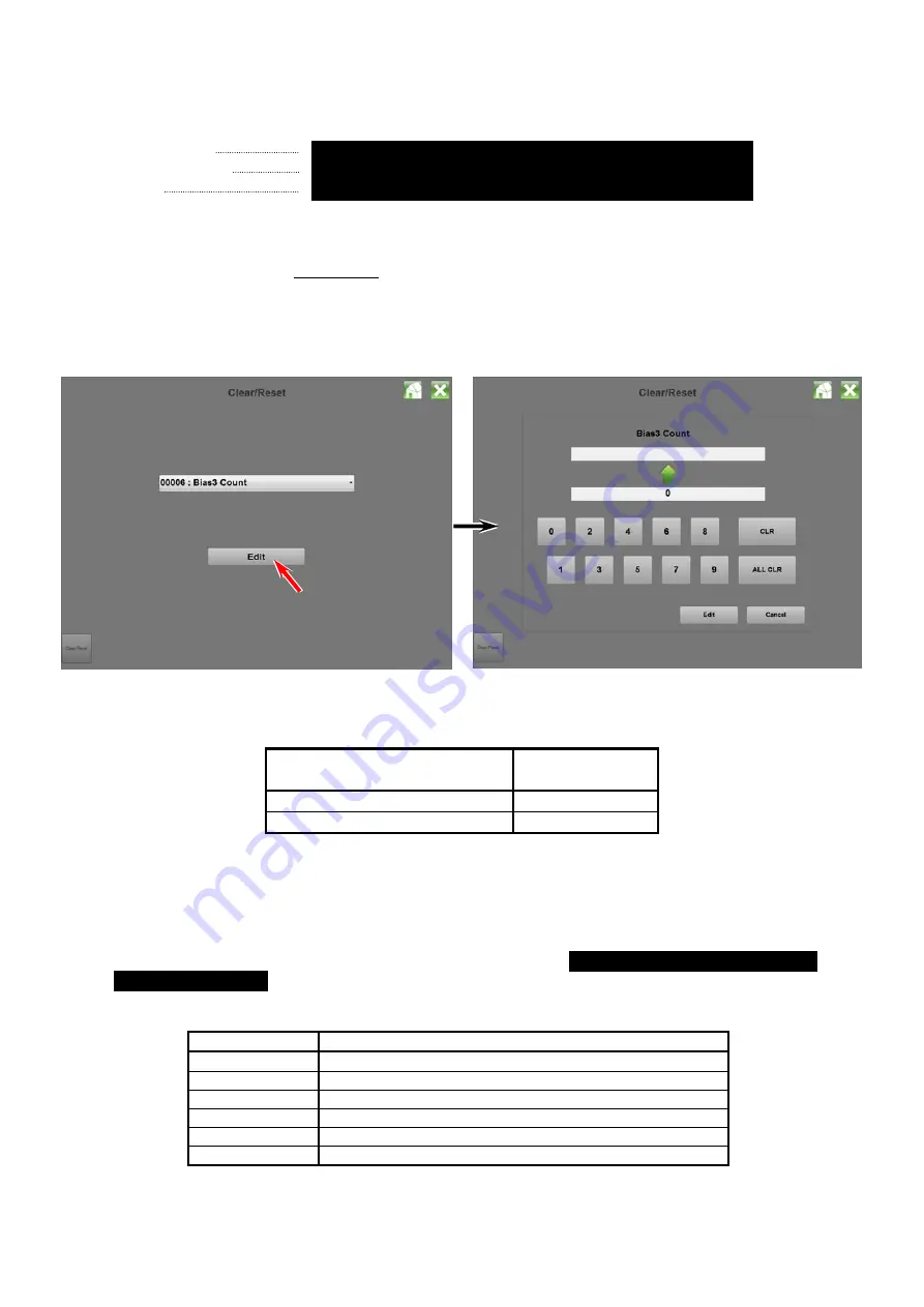
Enter [Clear/Reset]
Æ
“0006 Bias3 Count”
.
The voltage “-230V +/- 5V” is correct when the value shows
“1” / “2” / “3”
.
current Auto Adjustment Level
Supposed
Developer Bias
0
-180 +/-5V
1
/
2
/
3
-230 +/-5V
Refer to [8.11.3 Reset of Bias Adjustment by Density Compensation Process] for checking the
current Auto Adjustment Level.
If not satisfied, go to the next step for manual Developer Bias adjustment.
4. Select the Adjustment Mode, select each of following Sub Mode Numbers, and
change the setting value so that the output voltage satisfies
-180 +/-5V (CND Model : -200V)
against the ground
.
Refer to [8.4.3.11 Developer Bias (No.022 to 027)] for the detail.
Sub Mode No.
Contents
022
Developer Bias (Plain paper)
023
Developer Bias (Tracing paper)
024
Developer Bias (Film)
025
Developer Bias (Plain paper : Special)
026
Developer Bias (Tracing paper : Special)
027
Developer Bias (Film : Special)
Summary of Contents for 7170K
Page 1: ...KIP 7170K Service Manual Version A...
Page 46: ...K134sm2e5 2 28 7 Press GUIDES 8 Press Help 9 Press Settings SETTINGS screen appears...
Page 76: ...K134sm2e6 2 58 31 Type 4 with keypad and then click OK on the bottom 32 Click OK on the bottom...
Page 108: ...K134sm4e1 4 4 120V model 230V model 8 7 10 11 12 15 14 13 9...
Page 189: ...K134sm5e4 5 36 64 Press GUIDES 65 Press Help...
Page 384: ...K134sm5eH 5 231 3 Remove both Covers 3 5 6 pulling their sides outward 5 6...
Page 395: ...K134sm5eH 5 242 6 Remove the Blower 9 BL3 BL4 moving as the following photos 9 9...
Page 502: ...K134sm6e1 6 15...
Page 563: ...K134Ksm8e2 8 4 4 Press GUIDES 5 Press Help...
Page 564: ...K134Ksm8e2 8 5 6 Press Setting to indicate SETTINGS page...
Page 594: ...K134Ksm8e2 8 35 2 Press All Items 3 Press Export...
Page 747: ...K134Ksm8e7 8 188 8 9 2 Operation in Error Mask 1 Press Error Mask...
Page 749: ...K134Ksm8e7 8 190 8 9 3 Operation in Jam Mask 1 Press Jam Mask...
Page 750: ...K134Ksm8e7 8 191 2 Select the desired target...
Page 754: ...K134Ksm8e7 8 195 8 11 2 Changing Counter Value 1 Press Total Count 2 Press Edit...
Page 756: ...K134Ksm8e7 8 197 5 Press Edit to enable new value 6 Close the following message pressing OK...
Page 777: ...K134Ksm8e7 8 218 8 19 Communication Reset NOTE This function is not used in the market...
Page 839: ...K134sm8e8 8 280 29 Double click on the row No 15 Stitch Setting 1...
Page 863: ...K134sm9e1 Chapter 9 Appendix...
Page 864: ...KIP 7170 Overall Circuit Diagram USA 120V_KCS...


