


K134sm7e2
7-24
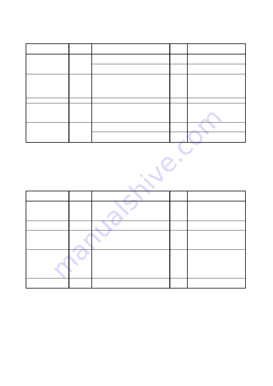
7. 2. 2. 4 Density is uneven
Check the following matters with the Pattern Print, pattern: #01_00 and pattern: #03_00.
If necessary use other Test Patterns.
Cause
Checking
order
Checking
Result
Treatment
Image Corona
1
Is the Image Corona dirty?
Yes
Clean the Image Corona, or
replace the Corona Wire.
Is the height of Corona Wire different
between left and right?
Yes
Adjust the height properly.
Installation of
Developer Unit
2
Is the Developer Unit firmly pressed
toward the Drum? (Do Counter Rollers
at both sides of the Developer Roller
touch the Drum Unit?)
No
Remove the Developer Unit,
and then install it to the
machine correctly.
Check the Developer Press
Unit.
LED Head
3
Is the Lens Array dirty
Yes
Clean it.
Eraser Lamp
4
Are all LED of the Eraser Lamp light
properly during the print?
No
1. Replace the Eraser
Lamp.
2. Replace the PW13420
PCB.
Developer Unit
5
Is the Developer Roller evenly covered
with the toner?
No
1. Clean Regulation Roller.
2. Reinstall Scraper.
Is the toner accumulating evenly in the
Developer Unit?
No
Level the machine correctly.
7. 2. 2. 5 Totally appeared foggy image
Check the following matters with the Pattern Print, pattern: #01_00 and pattern: #04_00.
If necessary use other Test Patterns.
Cause
Checking
order
Checking
Result
Treatment
1
Try to readjust each image creation
component according to [7.2.1 Basic
Image Adjustment].
Is the problem fixed?
Yes
OK
Developer Unit
2
Is the Developer Roller insulated from
the ground?
No
Check the Developer Roller
and connector.
Image Corona
3
Is the foggy image printed even if you
print a completely white pattern?
Yes
Check the output voltage
from the HV Power Supply
to the Image Corona.
If it is not correct, readjust it.
Developer Bias
4
Is the Developer Unit supplied with a
correct Developer Bias during the print?
No
Check the output voltage
from the HV Power Supply
to the Developer Unit.
If it is not correct, readjust it.
Or replace the HV Power
Supply PCB
Photoconductive
Drum
5
Have you used the Photoconductive
Drum longer than its part life?
Yes
Replace the
Photoconductive Drum.
Summary of Contents for 7170K
Page 1: ...KIP 7170K Service Manual Version A...
Page 46: ...K134sm2e5 2 28 7 Press GUIDES 8 Press Help 9 Press Settings SETTINGS screen appears...
Page 76: ...K134sm2e6 2 58 31 Type 4 with keypad and then click OK on the bottom 32 Click OK on the bottom...
Page 108: ...K134sm4e1 4 4 120V model 230V model 8 7 10 11 12 15 14 13 9...
Page 189: ...K134sm5e4 5 36 64 Press GUIDES 65 Press Help...
Page 384: ...K134sm5eH 5 231 3 Remove both Covers 3 5 6 pulling their sides outward 5 6...
Page 395: ...K134sm5eH 5 242 6 Remove the Blower 9 BL3 BL4 moving as the following photos 9 9...
Page 502: ...K134sm6e1 6 15...
Page 563: ...K134Ksm8e2 8 4 4 Press GUIDES 5 Press Help...
Page 564: ...K134Ksm8e2 8 5 6 Press Setting to indicate SETTINGS page...
Page 594: ...K134Ksm8e2 8 35 2 Press All Items 3 Press Export...
Page 747: ...K134Ksm8e7 8 188 8 9 2 Operation in Error Mask 1 Press Error Mask...
Page 749: ...K134Ksm8e7 8 190 8 9 3 Operation in Jam Mask 1 Press Jam Mask...
Page 750: ...K134Ksm8e7 8 191 2 Select the desired target...
Page 754: ...K134Ksm8e7 8 195 8 11 2 Changing Counter Value 1 Press Total Count 2 Press Edit...
Page 756: ...K134Ksm8e7 8 197 5 Press Edit to enable new value 6 Close the following message pressing OK...
Page 777: ...K134Ksm8e7 8 218 8 19 Communication Reset NOTE This function is not used in the market...
Page 839: ...K134sm8e8 8 280 29 Double click on the row No 15 Stitch Setting 1...
Page 863: ...K134sm9e1 Chapter 9 Appendix...
Page 864: ...KIP 7170 Overall Circuit Diagram USA 120V_KCS...


