background image

K134sm5eA 

5-114


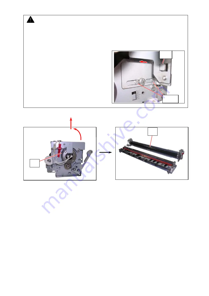
27.  Turn Fuser Upper Unit (39) to the back. Lift Fuser Upper Unit upward to remove it. 


NOTE 


Reinstall Bracket 2 (36) and Bracket 3 (38) in the correct position. 


(1) Fully push the bracket to the arrow direction so that the fold portion on the bracket will fit 

into the notch on Fuser Upper Unit. 


(2) The 2 positioning bosses locate the bracket.  

The bracket should not ride over them. 

39 

39 

fold 

boss 

Summary of Contents for 7170K

Page 1: ...KIP 7170K Service Manual Version A...

Page 2: ...wing two conditions 1 this product may not cause interference and 2 this product must accept any interference including interference that may cause undesired operation of this product Le pr sent appar...

Page 3: ...pearance 1 7 1 3 1 Front 1 7 1 3 2 Rear 1 8 1 4 Specifications for Scan Original 1 9 1 4 1 Original Standard 1 9 1 4 2 Special Documents 1 9 1 4 3 Do Not Scan Originals 1 10 1 5 Specifications for Pri...

Page 4: ...int resolutions with an enhanced scanning system produces the highest quality images controlled by an advanced KIP Image Process System 6 Easy access to USB port allows users to provide efficient prod...

Page 5: ...m Measurement method under UL Standard Dimensions In case of attaching UI Tray 1587mm Width x 704mm Depth x 1510mm Height In case of excluding UI Tray 1346mm Width x 704mm Depth x 1105mm Height Weight...

Page 6: ...rd length film Option 200 000mm Minimum 210mm 8 5 NOTE If the print is longer than the mentioned above its image quality or the reliability of paper feeding is not guaranteed Paper feeding method 2 Ro...

Page 7: ...F 4DME EU Asia model Plain Paper 64g m2 to 80g m2 Tracing Paper Gateway Tracing Paper 73g m2 Film NSF4mil Storage of consumables Toner cartridge Store the cartridge within the temperature range from 0...

Page 8: ...mm Scan length Max 6 000mm 19 7ft Including the margin area Min 210mm 8 5 Including the margin area NOTE If the print is longer than 6 000mm its image quality or the reliability of paper feeding is no...

Page 9: ...an or copy 7 Toner Hatch Original Table Open the Toner Hatch when you replace the Toner Cartridge Also put the original here and then feed it into the Scanner Unit when you make scan or copy 8 Engine...

Page 10: ...al device Service Use 5VDC max 4 LAN Port Connect the LAN Cable to connect the KIP 7170 to the network Do not connect a telephone line 5 Dehumidify Heater Switch US model OPTION EU Asia model Standard...

Page 11: ...range from 0 05mm to 0 25mm 4 The shape of original must be square and it must be standard sized 5 The type of original must belong to any of the followings Plain paper Coated paper High or middle cla...

Page 12: ...e following types of originals because they are likely to damage the scanner Do not scan the following kinds of original because you may damage the original or scanner itself Sticked with paste Torn F...

Page 13: ...K134sm1e1 1 11 Not square Wet image Made of metal or fabric Rough surface Carbon paper for example Clipped or stapled Wet Metal Fabric Clipped Stapled Rough surface...

Page 14: ...K134sm1e1 1 12 The following kinds of originals can be read with using a carrier sheet However the image quality and feed reliability are not guaranteed Patched Punched...

Page 15: ...ications for Printing Media 1 5 1 Papers not available to use Do not use the following kinds of printing paper because you may damage the print engine Excessively curled a diameter of 50 mm or less Fo...

Page 16: ...use for the fire NOTE 1 Print image may become light if printed on a paper of rough surface 2 Print image may become defective if the print paper is much curled 3 It will become a cause for paper mis...

Page 17: ...se and keep it in a polyethylene bag Void of image occurs when you print with plain paper and tracing paper If you will not make print soon remove the tracing paper from the machine and keep it in a p...

Page 18: ...2 10 Scanner Adjustment 2 40 2 10 1 Launching K129 Diag 2 40 2 10 2 Stitching Adjustment 2 44 2 10 3 Creating Backup Data 2 60 The machine had passed our strict inspection after careful adjustment in...

Page 19: ...lation site must not have any open flames dust or ammonia gases 2 The equipment must not be exposed to the air vents from heating cooling systems 3 The equipment should not be exposed to the direct su...

Page 20: ...k Inside Exit Tray Box 5 2 Lift up both sides 6 of the Scanner Unit and then remove the protection mat 7 Gently press Scanner Unit down and firmly close it 1 2 UI Unit Box Monitor Assembly Tooth Washe...

Page 21: ...of article Item name Picture Number of article Original Guide 1 2 1 each Cap Assy 4 Toner Cartridge 400g 2 Power Cord 1 User s Manual CD Rom 1 Setup Procedure 1 This leaflet User s Manual German 1 UI...

Page 22: ...Tray Box Item name Picture Number of article Item name Picture Number of article Exit Tray 2 Exit Tray 2 1 Others Item name Picture Number of article Item name Picture Number of article Shading Sheet...

Page 23: ...0 1 Pull up the Lever 2 1 to open the Engine 2 Remove the screws 2 at both sides 3 Remove 4 screws 3 at the bottom of both sides 4 Remove 6 screws 4 at the back on both sides 5 Remove the Cover 2 5 an...

Page 24: ...m plate and the floor It is about 80mm before the adjustment 8 Put a level 8 on the specified positions shown to check the level of the KIP 7170 If not leveled adjust by rotating the Adjustment Bolts...

Page 25: ...4sm2e3 2 7 2 4 Setup of the Machine 1 Draw out Roll Deck and remove tape 1 2 Pull up on the Levers 1 to open the Engine 3 Carefully remove the protection mat 3 under the Drum 4 Open the Cover 4 4 2 3...

Page 26: ...move the screws 5 and flat washers 6 to release the Bands 7 at both sides 6 Rotate up the Pins 8 and move them to the inside to pull them out from the holes Remove the Cover 4 4 7 Open the Bypass Feed...

Page 27: ...Feeder 9 Open the Developer Press Unit 11 9 Disconnect the connector 12 11 Remove 2 pieces of red screw 13 at both sides of the Developer Unit which protect the Developer Unit from vibration during t...

Page 28: ...13 Remove 1 label 15 on the toner supply hole of Toner Hopper 14 Remove 8 labels 16 17 to remove wrapping sheet 18 15 The process unit and toner cover should be open The Photoconductive Drum is covere...

Page 29: ...achine side and the Gear Helical 28T 21 on Developer Unit side must be in gear firmly with each other but they may not be in gear with each other by just installing the Developer Unit to the machine A...

Page 30: ...ion After that pressing the Fix Bracket 23 from above fix the screw 22 Left side Right side 22 23 23 22 NOTE Please satisfy the following requirements before performing Step 19 1 The black sheet has b...

Page 31: ...ct the connector 5 and open the wire saddles 6 to release the harness To keep the proper gap between the LED Head and the Drum make sure to open and close the LED Head Frame According to this work the...

Page 32: ...K134sm2e3 2 14 4 Open the Cover 4 7 5 Remove 4 pieces of 4x6 screw 8 and 2 pieces of washer screw 9 6 Slide the Scanner Unit 10 fully backward 7 8 8 9 9 8 8 10...

Page 33: ...osen the screw 12 and then slide the Stoppers 11 outside to unlock the LED Head Frame 8 Open the LED Head Frame 13 12 11 NOTE The Stopper 2 14 comes out automatically to prevent the LED Head Frame fro...

Page 34: ...ge the order of these steps 1 Close the LED Head Frame 2 Surely press down and hold the left side of LED Head Frame as A completely push the white plastic Stopper into the hole as B and tighten the sc...

Page 35: ...K134sm2e3 2 17 10 Return the Scanner Unit 10 in position 11 Fix the Scanner Unit with 4 screws 8 and 2 tooth washer screws 9 10 8 8 9 9 8 8...

Page 36: ...12 Close the Cover 4 7 13 Connect the connector 5 and then fix the DC Harness and USB Cable with Wire Saddle 6 14 Attach the Cover 10 4 with 2 screws 15 Close the Paper Exit Assy Outside 1 Inside 2 4...

Page 37: ...19 2 6 Installing Monitor 1 Insert 2 Tooth Washer Screws 1 into the screw hole on the right side frame of the machine 2 Hook Monitor Assy 2 on the Tooth Washer Screws 1 Tighten 2 Tooth Washer Screws...

Page 38: ...K134sm2e4 2 20 3 Fix Monitor Assy with 2 Tooth Washer Screws 3 4 NOTE Please use the screw driver which length is 24cm 9 4 inch or shorter when tightening the screws 4 24cm 9 4 inch or shorter 2 3 2 4...

Page 39: ...he Cover 2 9 and the Cover 3 10 Monitor Assy can be turned up down and right left Adjust the movement by the concerning screw NOTE Be sure to insert the USB plug of the USB Cables 5 8 to the correct r...

Page 40: ...4sm2e5 2 22 2 7 Installing Accessories 1 Install Exit Tray 1 Original Guide 2 and Exit Tray 2 3 NOTE Install Exit Tray 2 3 in the correct direction The spine should face down Correc Wrong Side View 3...

Page 41: ...ssing down the Cartridge Lock Lever 6 Direct the toner supply hole to the floor fit the pin 7 on the left side of the cartridge to the groove 8 on the machine side NOTE Please confirm that the Cartrid...

Page 42: ...he arrow direction to open the toner supply hole Confirm that the projection 10 if fitted into the notch 11 6 Close Cover 4 4 NOTE It is not necessary to lock the cartridge with the Lever 12 Lever 12...

Page 43: ...dedicated wall outlet WARNING 1 Do not handle the Power Plug with wet hands or you may receive an electrical shock 2 Make sure to ground the machine for safety 3 Do not plug the printer into a multi w...

Page 44: ...K134sm2e5 2 26 2 Connect Power Cable and LAN Cable with the printer 3 Press side to turn on the printer Power Cable Press side LAN Cable...

Page 45: ...UNTING 5 Touch the entry field of User Name and then select Service from the pull down menu 6 Enter kipsysk in the password field press the ENTER key and then press OK in the LOG IN screen to log in w...

Page 46: ...K134sm2e5 2 28 7 Press GUIDES 8 Press Help 9 Press Settings SETTINGS screen appears...

Page 47: ...10 Press LANGUAGE Select a language 11 Press DATE TIME Select your time zone in Time Zone region and then Press OK 12 Press DATE TIME again Change Date and Time settings according to your region and...

Page 48: ...Server if necessary and then press OK after NOTE Depending on the network environment in which the printer is installed IPV6 SETUP is sometimes used For this case please perform the network setting w...

Page 49: ...lected touch the entry screen enter the IP Address with the software keyboard and then press Enter Key After that press OK on the SETTINGS screen 16 Press PRINTERE NAME and press EDIT Entry screen app...

Page 50: ...r name and then press Enter Key 18 When pressing SAVE the screen for restarting the controller appears Press RESTART The printer name is defined by this operation 19 After rebooting the controller ope...

Page 51: ...K134sm2e5 2 33 20 Press Edit Touch the entry screen enter Key Code and then press SAVE 21 If the entered key code is correct the corresponded option s is checked Press Close Touch...

Page 52: ...ens the toner level in it It takes approximately 20 minutes to complete Reference 1 On the status indication in the upper right Warming Up is displayed while supplying the toner and Ready is displayed...

Page 53: ...ording to the destination of the product At any region please be sure to reconfirm the setting value and correctly change if it is not correct for the actual region of installation NOTE Selected regio...

Page 54: ...K134sm2e5 2 36 3 Press Door Icon to log in Maintenance GUI Home 4 Press Map Icon in Maintenance GUI Home...

Page 55: ...o selection 01 NA North America Canada 02 EUR EU Russia 03 CLA Central America South America 04 AAP Asia except China Middle East Africa Oceania 05 CN China including Hong Kong 06 JP Japan 07 OT All o...

Page 56: ...econds later This will enable the selected regional setting 8 When the printer is turned on it indicates the log in page of Maintenance GUI OFF ON NOTE Selected regional setting will become effective...

Page 57: ...K134sm2e5 2 39 9 Press X button Confirmation screen appears Press Yes 10 UI screen will display Home screen in a short time...

Page 58: ...ner Adjustment 2 10 1 Launching K129 Diag On the UI Home screen press the Home icon and the status indication quickly in the following order to indicate the desktop screen KIP icon twice Status indica...

Page 59: ...K134sm2e6 2 41 2 Open Diagnostics folder 3 Double click Hardware Utilities and K129 diag X X X X XX...

Page 60: ...K134sm2e6 2 42 4 Run K129 Diag Other ways to run the K129 Diag are described on the next page Reference...

Page 61: ...rtner for K129Diag exe and save it to any available storage on your removable storage Connect removable storage to UI monitor s connector 2 Select Removable Disk and then run K129 Diag exe Reference R...

Page 62: ...2 44 2 10 2 Stitching Adjustment 1 Run K129 Diag Click BackupData to recall Backup Data sub window 2 Click Receive NOTE BUD No 15 stitch setting 1 should be temporarily set to OFF 0 during Stitching A...

Page 63: ...K134sm2e6 2 45 3 The current parameters are retrieved and displayed in the list 4 Double click on the row No 15 Stitch Setting 1...

Page 64: ...K134sm2e6 2 46 5 In FormInput screen Click Virtual Keyboard to display the screen keypad 6 Type 0 with keypad and then click OK on the bottom 7 Click OK on the bottom...

Page 65: ...K134sm2e6 2 47 8 The setting change you have made is reflected to the list It will turn blue Click Send on the bottom The setting change turns black Now it is sent to the Main Board...

Page 66: ...he X button at the upper right corner 10 Clean Glass DCMNT with a soft cloth 11 Set the Shading Sheet to the scanner noting the arrow direction 12 Click Motion to recall Motion sub window NOTE No skew...

Page 67: ...hing Adjustment in the upper drop down menu 14 Click Start beside the upper drop down menu NOTE If an error message occurs 1 Correctly set the Shading Sheet to the scanner 2 Check for dirt on the Glas...

Page 68: ...K134sm2e6 2 50 15 When the scanning is finished two sub windows Stitch Simulate and Stitch Adjust appear Enlarge StitchAdjust window Enlarge Stitch Adjust window...

Page 69: ...Stitch Adjustment window Select Jump menu and then click CIS1 to CIS2 The display area will jump to the corresponding area on the scanned image If Jump does not move to the target exactly manually scr...

Page 70: ...e results If all of the 4 targets have no misalignment go to step 25 If any of the targets has an misalignment go to step 19 and after for manual correction vertical Go to step 19 horizontal Go to ste...

Page 71: ...ing value in red is not finalized yet Click Send Once the change is sent to the scanner s Main Board setting values turn black vertical misalignment or this may include vertical horizontal misalignmen...

Page 72: ...ixel to right 20 2 Image shifting setting value in red is not finalized yet Click Send Once the change is sent to the scanner s Main Board setting values turn black horizontal misalignment NOTE 1 For...

Page 73: ...rrection result on the 4 targets If there is still misalignment go back to step 19 and 20 to remove it 22 Set the Shading Sheet to the scanner noting the arrow direction Be sure to reconfirm the manua...

Page 74: ...onfirm Scan to make another scan 24 The rescan result can be checked in StitchAdjust window 25 Click the X button at the upper right corner to close StitchAdjust and StitchSimulate sub windows 26 Run...

Page 75: ...4sm2e6 2 57 28 The current parameters are retrieved and displayed in the list 29 Double click on the row No 15 Stitch Setting 1 30 In FormInput screen Click Virtual Keyboard to display the screen keyp...

Page 76: ...K134sm2e6 2 58 31 Type 4 with keypad and then click OK on the bottom 32 Click OK on the bottom...

Page 77: ...K134sm2e6 2 59 33 The setting change you have made is reflected to the list It will turn blue Click Send on the bottom The setting change turns black Now it is sent to the Main Board...

Page 78: ...Data If you have quitted Backup Data window in the previous section click Backup Data in the home screen click Receive To easily recover the scanner in case of lost crash of the BUDs follow the instr...

Page 79: ...K134sm2e6 2 61 1 Select File menu and click Save As 2 Specify the location to create a backup csv and then click Save...

Page 80: ...Click the X button to quit BackupData sub window and K129 Diag 4 Run Touch UI Home screen reappears 5 Turn off the printer After confirming that the controller is surely shut down turn on the printer...

Page 81: ...rum 3 6 3 1 2 3 Exposure 3 7 3 1 2 4 Development 3 8 3 1 2 5 Transfer 3 10 3 1 2 6 Separation 3 11 3 1 2 7 Drum Cleaning Removal of remained toner 3 12 3 1 2 8 Fusing 3 13 3 1 3 Controlling the moveme...

Page 82: ...al Relatively positive On the contrary suppose that the toner exists on the object B of which electric potential is higher than the object A Even if you move the object A close to the object B the ton...

Page 83: ...ric charges 2 Charge of Drum 3 Exposure 4 Development 5 Transfer 6 Separation 7 Drum Cleaning Removal of remained toner 8 Fusing Image Corona LED Head Cleaning Roller Eraser Lamp Regulation Roller Ton...

Page 84: ...sides 0V Connected to the ground 0V Connected to the ground Toner Supply Roller The same voltage with Developer Roller Bias The same voltage with Developer Roller Bias Transfer Corona Plain Paper 1 2m...

Page 85: ...rum which have remained there after the former print cycle The Drum has a characteristic to lose the negative electric charges if it is exposed to the light So the Drum is rotated and evenly exposed t...

Page 86: ...rum becomes about 620V evenly as a result which corresponds to the white area of the printed image pattern The Grid Plate is also connected to the High Voltage Power Supply individually Current and Vo...

Page 87: ...part of Drum surface which was not exposed to the light from the LED Head keeps 620V of potential which the Image Corona has given An invisible electric image pattern that consists of 620V area and th...

Page 88: ...Exposure process Seen from the voltage of Developer Roller Bias 180V CND Model 200V the 20V area on the Drum is relatively positive So the toner moves from the Developer Roller to the 20V area of Drum...

Page 89: ...the Drum to the Developer Roller 3 Developer Roller carries the toner toward the Toner Supply Roller 4 Toner is shifted to the inside of the Developer Unit by the revolution of Toner Supply Roller 5 T...

Page 90: ...20V area on the Drum will move to the printing paper because the potential of the paper comes to be higher than the Drum by the Transfer Process The voltage supplied to the Transfer Corona Wire is as...

Page 91: ...age is compensated by the negative DC voltage the negative charges are generated more than positive ones which mainly results in removing the positive charges of the printing paper On the other hand t...

Page 92: ...some negative electric charges on the Drum at this time As the Cleaning Roller is relatively positive and the Drum is negative the toner moves from the Drum to the Cleaning Roller 450V NOTE If too muc...

Page 93: ...r Unit mainly consists of the Fuser Roller and the Pressure Roller The Fuser Roller is very hot and the Pressure Roller is strongly pressed to the Fuser Roller by the spring The toner is firmly fused...

Page 94: ...200V 5V against the ground CND Model Regulation Roller Center 80V 5V against the Developer Roller Bias Regulation Roller Both sides 0V Connected to the ground Toner Supply Roller The same voltage wit...

Page 95: ...Regulation Roller limits the amount of toner that can pass through between 2 rollers So very small amount of toner can pass through between rollers and the rest is returned back to the inside As the...

Page 96: ...Roller The side areas of the Developer Roller are not covered with the toner as a result so it is possible to avoid the toner drops into the machine from the side Regulation Roller Both Sides 0V Conne...

Page 97: ...to another because the print size specified in the job is different This process to return the toner is called Toner Collection Process When the trailing edge of the last sheet passes over the Separa...

Page 98: ...er Collection Process As the potential of Developer Roller becomes higher than that of Drum toner on the Drum moves onto the Developer Roller Then the toner is carried into the Developer Unit by both...

Page 99: ...gainst the Developer Roller Bias Developer Roller Toner Supply Roller 350V against GND Same voltage with the Developer Roller Bias Reference Name of roller Supplied voltage Developer Roller 350V 5V ag...

Page 100: ...is measured by Density Sensor Density Measure The average of the patches Density Value is calculated 3 If the Density Value does not meet Target Density Developer Regulation Bias will be automatically...

Page 101: ...rd takes a proper image process according to the settings configured with K129 Diag It outputs the image data to the Controller through the USB 2 0 4 Controller outputs the image data to the KIP print...

Page 102: ...ind of problem it is necessary to remove the duplication of image pixels by horizontal positioning process X overlap The Main PCB performs these positioning processes Explanation 5 pieces of CIS are a...

Page 103: ...CB removes the vertical gap among the Image Block according to the positioning setting Y offset specified through K 129 Diag The image data before the positioning process The image data after the posi...

Page 104: ...the duplication of image pixels among the Image Blocks according to the positioning setting X overlap specified through K 129 Diag The image data after the positioning process Y offset The image data...

Page 105: ...tment of Analog Output from HV Power Supply 4 30 4 3 1 Situations necessary to check the analog output 4 30 4 3 2 Analog Voltage to Image Corona 4 31 4 3 3 Analog Voltage to Transfer Corona 4 33 4 3 4...

Page 106: ...ring is separated depends on the voltage 0VDC Blue 5VDC Yellow 12VDC Brown 24VDC Orange Signal in to DC Controller sensors Purple Signal out from DC Controller Gray Sensor Micro Computer CPU ROM DC Lo...

Page 107: ...trol of the Fuser 4 SSR2 Solid State Relay AQJ416V US AQJ426V EU ON OFF control of the Fuser 5 HV1 HV2 HV3 HVP4 HV_IM HV_TR HV_AC HV Power Supply EUK1MGA60HA Outputting the high voltage to each of the...

Page 108: ...K134sm4e1 4 4 120V model 230V model 8 7 10 11 12 15 14 13 9...

Page 109: ...r 10 RY1 Relay G7L 2A TUB DC24V Supplying the power to the Lamp H1 H2 It stops supplying the power to the Lamp when Switch MS3 or Thermostat TS1 TS2 is open 11 LF1 Noise Filter Removing the noise from...

Page 110: ...Assy PW6654 02B Driver for the motors clutches and so on 3 MS4 Switch V 162 1C25 10E Detecting whether or not the Toner Hatch or the left side of Engine Unit is opened The machine does not shut off th...

Page 111: ...72 90 Cooling down the IPS Controller 3 DCP2 DC Power Supply ZWS75BAF12 Supplying the DC power to both the UI and the PW11724 4 PW11724 PW11724 PCB ASSY PW11724 Lightning surge protector Shutting down...

Page 112: ...K134sm4e1 4 8 Fuser Unit omitted Item Symbol Signal name Name Type Function 7 BL5 Fan ASFN60372 Supporting media feeding approach 8 BL6 Fan ASFN60372 Supporting media feeding approach 7 8...

Page 113: ...K134sm4e1 4 9 Item Symbol Signal name Name Type Function 9 MS8 Switch Optional in USA FA2L BA22 It stops supplying the AC power to the Dehumidify Heater when the Roll Deck is opened 9...

Page 114: ...are equipped with the Ozone Filter 11 MS2 Switch FA1L AA22 Shuts off the AC power to the DCP1 when the right side of Heater Hatch is opened 12 MS3 Switch V 162 1C25 10E Detecting whether or not the le...

Page 115: ...34sm4e1 4 11 4 2 4 LED Head Frame Item Symbol Signal name Name Type Function 1 PW6631 ER1 Eraser PCB A PW6631 Removing the negative electric charges from the Drum at the beginning of the Print Process...

Page 116: ...it removed Item Symbol Signal name Name Type Function 2 LED HEAD LED Head Assy LH6604 53TRK x 3pcs Creating latent Images on Drum 3 PW6693 HV ZD Assy PW6693 Keeping the Grid Voltage constant Control o...

Page 117: ...n 1 PW6631 ER2 Eraser PCB A PW6631 Assisting the paper separation by removing the electric charges from the Drum at the time of Separation Process 2 DENS S PH11 Toner Density Sensor GP2Y40010K0 F Dete...

Page 118: ...um Or keeping the Developer Unit away from the Drum 4 PH4 PRESS_S Sensor GP1A73LCS2F Or GP1A73A000J Detecting the Developer Unit is pressed or kept away 5 PH1 REGIST_S Sensor PS117ED1 Detecting the pa...

Page 119: ...K134sm4e1 4 15 Item Symbol Signal name Name Type Function 7 MS5 DOOR OPEN Switch CS1A B2CA Detecting the Roll Deck Open Error 7...

Page 120: ...TLS1 TONER_S Sensor TSP15DA10C 01 Detecting whether or not the toner exists in the Developer Unit 2 M3 TONER_M Motor Set Geard MA D05 008 Driving the Toner Hopper to supply the toner to the Developer...

Page 121: ...Type Function 1 TS1 TS2 Thermostat CH 152 35 170 Preventing over heat 2 TH1 TH1 Thermistor FS K0113 Detecting the temperature on the central area of Fuser Roller 3 TH2 TH2 Thermistor 3 FS K0115 Detect...

Page 122: ...amp 120V Z166800001 230V Z166800003 Heating up the central part of Fuser Roller 5 H2 Lamp 120V Z166800002 230V Z166800004 Heating up the right and the left part of Fuser Roller 6 PH3 HEAT_EXIT Sensor...

Page 123: ...pe Function 7 SL1 STACK_SL Solenoid STC SN10E Deciding print path to either top rear 8 PH15 STACK_S Sensor GP1A73LCS2F Or GP1A73A000J Detecting stacked prints 9 PH16 STACKJ_S Sensor GP1A73A000J Detect...

Page 124: ...tch MIC8NE 23 Feeding the Roll 1 forward 3 CL5 R1BK_CL Clutch MIC8NE 09 Rewinding the Roll 1 4 CL6 R2FD_CL Clutch MIC8NE 23 Feeding the Roll 2 forward 5 CL7 R2BK_CL Clutch MIC8NE 09 Rewinding the Roll...

Page 125: ...H4 H5 H6 Resister 120V 1K 15W 230V 3 5K 15W Dehumidifying the roll paper 9 TS3 TS4 TS5 TS6 Thermostat 2455RM 158 37 Controlling the temperature of Resister The Resisters turn on when the Thermostat de...

Page 126: ...D1 Detecting the trailing edge of the roll paper 11 PH7 R1SET_S Sensor PS117ED1 Detecting the set of Roll 1 12 PH12 FEED_ENC Sensor GP1A73LCS2F Or GP1A73A000J Detecting the length of the proceeding pa...

Page 127: ...34sm4e2 4 23 4 2 9 Cutter Unit Item Symbol Signal name Name Type Function 1 M5 Cutter Motor Moving the Cutter Blade 2 MS6 MS7 Cutter Home Position Sensor Detecting the Home Position of Cutter Blade 1...

Page 128: ...K134sm4e2 4 24 4 2 10 Inner Transport Unit Item Symbol Signal name Name Type Function 1 PH2 STRIP_S Sensor GP1A73A000J Detecting the paper mis feed at the Separation Area 1...

Page 129: ...Function 1 PW12930 01 LED DISPLAY BOAD ASSY PW12930 01 Indicates the scanner s status green Ready green to and fro Scanning red Error red flashing Cover Open Jam 2 PW12975 01 SW CONTROL BOARD ASSY PW1...

Page 130: ...PW12920 D CON Data Controller PCB PW12920 02 Converts the analog data sent by CIS into digital data Then takes some image processes to the digital data and sends it to KIP Printer via USB cable 4 S_P...

Page 131: ...etects original width A4 Portrait 6 S_PH2 Sensor PS122GD4 A Detects original widths A4 Landscape A3 11 and 12 7 S_PH3 Sensor PS122GD4 A Detects original widths A2 17 and 18 8 S_PH4 Sensor PS122GD4 A D...

Page 132: ...K134sm4e2 4 28 Item Symbol Signal name Name Type Function 12 M6 Motor 103H7123 5746 Transports the original 13 S_PH9 Sensor LG248BL1 Detects rotations of FEED ROLLER 12 13...

Page 133: ...Corona 4 34 DC Component to the Separation Corona 4 36 Negative Developer Bias to the Developer Roller 4 38 Positive Developer Bias to the Developer Roller 4 40 Bias gap between Developer Roller and R...

Page 134: ...ble of the multi meter to the CP11 pin on the HV Power Supply PCB EUK1MGA60HA Also connect the one to the CPCOM And then select the DC volt range on the multi meter 2 Make a Test Print making referenc...

Page 135: ...K134sm4e3 4 31 3 Adjust the output voltage if it does not satisfy 1 30 0 05V To adjust it rotate the VR101 with a screwdriver VR101 multimeter DC...

Page 136: ...Film 1 00 0 05V Check and adjust the output current in the following way 1 Connect the cable of the multi meter to the CP21 pin on the HV Power Supply PCB EUK1MGA60HA Also connect the one to the CP22...

Page 137: ...ing paper 1 00 0 05V Film 1 00 0 05V 3 Adjust the output voltage if it does not satisfy the above specifications Select the Adjustment Mode select each of following Sub Mode Numbers and change the set...

Page 138: ...cable of the multi meter to the CP31 pin on the HV Power Supply PCB EUK1MGA60HA Also connect the one to the CPCOM pin And then select the DC volt range on the multi meter 2 Make a Test Print making re...

Page 139: ...K134sm4e3 4 35 3 Adjust the AC Component if it does not satisfy 5 00 0 05V To adjust it rotate the VR302 with a screwdriver VR302 multimeter DC...

Page 140: ...cable of the multi meter to the CP33 pin on the HV Power Supply PCB EUK1MGA60HA Also connect the one to the ground And then select the DC volt range on the multi meter 2 Make a Test Print making refe...

Page 141: ...K134sm4e3 4 37 3 Adjust the DC Component if it does not satisfy 250 5V To adjust it rotate the VR303 with a screwdriver VR303 multimeter DC ground...

Page 142: ...against the ground 200 5V CND Model Film 180 5V against the ground 200 5V CND Model Check and adjust the Negative Developer Bias in the following way 1 Connect the cable of the multi meter to the OUT...

Page 143: ...nsation Process it is set as OFF Enter Clear Reset 0006 Bias3 Count The voltage 230V 5V is correct when the value shows 1 2 3 current Auto Adjustment Level Supposed Developer Bias 0 180 5V 1 2 3 230 5...

Page 144: ...eaning Cycle The standard value of the Positive Developer Bias is 0 350 0 005V against the CP42 Check and adjust the Negative Developer Bias in the following way 1 Connect the cable of the multi meter...

Page 145: ...inted paper has been ejected Check the voltage with the multi meter during that period The standard value of the Positive Developer Bias is 0 350 0 005V against the CP42 If this is not satisfied go to...

Page 146: ...EUK1MGA60HA Also connect the one to the OUTPUT2 pin And then select the DC volt range on the multi meter 2 Make a Test Print making reference to 8 3 Pattern Print As the Bias is supplied to both the D...

Page 147: ...ows 2 The voltage 160V 5V is correct when the value shows 3 current Auto Adjustment Level Supposed Bias Gap 0 1 80 5V 2 120 5V 3 160 5V Refer to 8 11 3 Reset of Bias Adjustment by Density Compensation...

Page 148: ...n the following way 1 Connect the cable of the multi meter to the OUTPUT 5 pin on the HV Power Supply PCB Also connect the one to the ground And then select the DC volt range on the multi meter 2 Make...

Page 149: ...K134sm4e3 4 45 3 Adjust the Positive Cleaning Roller Bias if it does not satisfy 450 5V To adjust it rotate the VR001 with a screwdriver VR001 multimeter DC ground...

Page 150: ...ck and adjust it in the following way 1 Connect the cable of the multi meter to the OUTPUT 5 pin on the HV Power Supply PCB Also connect the one to the ground And then select the DC volt range on the...

Page 151: ...K134sm4e3 4 47 3 Adjust the Negative Cleaning Roller Bias if it does not satisfy 550 5V To adjust it rotate the VR002 with a screwdriver multimeter DC ground VR002...

Page 152: ...er Pressure Adjustment NIP width check 5 117 5 3 6 Replacement of Thermistor TH1 TH2 5 118 5 3 7 Replacement of Thermostat TS1 TS2 5 120 5 3 8 Replacement of Exit Sensor PH3 5 121 5 4 Roll Deck 5 127...

Page 153: ...f Manual Set Sensor PH5 Registration Sensor PH1 5 237 5 9 3 Replacement of Fans BL5 BL6 5 239 5 9 4 Replacement of Blowers BL3 BL4 5 240 5 10 Inner Transport Unit 5 243 5 10 1 Removal of the Inner Tra...

Page 154: ...34sm5e2 5 1 5 1 Outer Covers 5 1 1 Removal of Side Covers 1 Remove 2 pieces of Exit Tray 1 and Exit Tray 2 2 2 Pull up the Lever 2 3 to open the Engine Unit 3 Remove the screws 4 at both sides 3 4 4 1...

Page 155: ...K134sm5e2 5 2 4 Remove 4 pieces of screw 5 at both sides 5 Remove 6 pieces of screw 6 at both sides 6 Remove both Cover 2 7 and Cover 3 8 5 6 7 8 6 5...

Page 156: ...K134sm5e2 5 3 5 1 2 Removal of Cover 15 1 Remove 4 pieces of screw 1 loosen 4 pieces of screw 2 and then remove the Cover 15 3 1 2 3...

Page 157: ...f Top Cover 1 Remove 2 pieces of Exit Tray 1 and Exit Tray 2 2 2 Remove 4 screws 3 on the back 3 Lift up both sides of the Upper Unit 4 4 Remove 2 screws 5 to remove the Front Cover 6 middle 3 1 2 4 L...

Page 158: ...K134sm5e2 5 5 5 Disconnect 1 connector 7 6 Remove 4 screws 8 on the front 7 Remove the Top Cover 9 8 8 7 NOTE For reassembling fit the front end of the Top Cover to the Upper Unit 9...

Page 159: ...2 Developer Unit 5 2 1 Removal of the Developer Unit 1 Remove 2 pieces of Exit Tray 1 and Exit Tray 2 2 2 Open the Cover 4 3 3 Remove the 4x6 screws and washers 4 at both sides to make the Bands 5 fre...

Page 160: ...en slide them inward to remove the Cover 4 3 5 Pull up the Lever 2 7 to open the Engine Unit 6 Open the Bypass Feeder 8 3 6 6 7 NOTE It is impossible to remove the Developer Unit if the Engine Unit is...

Page 161: ...he connector 11 Holding both Side Plates 12 remove the Developer Unit 13 from the machine 10 9 9 8 8 NOTE If you replace the whole Developer Unit it is necessary to adjust the space between developer...

Page 162: ...ion Refer to this section as well for replacement individual part listed below 2 Remove all the toner from Developer Unit before replacing the above parts 3 After replacing Developer Blade Rollers an...

Page 163: ...K134sm5e3 5 10 3 Remove 4 pieces of 4x6 screws 2 to remove the Hopper Assembly 3 4 Remove 3 pieces of M4x6 screws 4 to remove Cover 5 5 Remove Separator 6 5 4 3 6 6 2 2...

Page 164: ...x6 screw 7 to remove Scraper Assembly 8 7 Loosen 10 screws 9 to remove Scraper from Scraper Assembly 8 7 7 8 9 9 NOTE Just loosen the screws as little as possible to remove Scraper Doing so will reduc...

Page 165: ...e face can be read in correct orientation 9 Adjust Scraper so that its side edges stick out in 1 to 2mm from the side rim of the bracket Then temporarily tighten the screws on both ends NOTE Visually...

Page 166: ...5 Z054601260 to the bracket s inside to reduce the gap 13 Again check for wave on Scraper s edge If it is OK rub toner powders on the edge NOTE Be sure to check for wave on Scraper s edge If there is...

Page 167: ...15 is pressed onto released from Developer Roller 16 by Bracket 4 17 on the driving side and Bracket 5 18 on the electrode plate side When reassembling Blade Roller 15 should be pressed onto Roller De...

Page 168: ...ollar 23 17 Remove Washer 24 8 1x14x0 5t and Gear 29T 34T Assy 25 18 Remove Gear Helical 30T 26 and Parallel Pin 27 3x20 from Toner Supply Roller shaft If you cannot remove Parallel Pin 27 at this tim...

Page 169: ...r 32 12 2x20x0 5t and Counter Roller 33 from Developer Roller shaft 21 Remove 2 screws 34 M4x8 to remove Bracket 4 17 and Spring 35 At this time Blade Roller on the driving side will be released from...

Page 170: ...ollar 40 and Bracket 10 Assy 41 24 Remove Gear Helical 30T 42 and Parallel Pin 43 3x16 from Toner Supply Roller shaft 25 Remove Washer 44 12 1x20x0 2t Gear Helical 25T 45 Parallel Pin 46 3x16 Counter...

Page 171: ...ed Bracket 5 18 27 Loosen 2 screws 50 to remove Bracket 19 51 28 On the driving side remove 1 pan head screw 52 M4x8 W SW FW to remove 1 flat washer 53 M4 and Bracket 6 Assy 54 29 On the electrode pla...

Page 172: ...ler at this time 31 On the driving side remove 3 screws 60 M4x6 and Retaining Ring E 61 E10 to remove Washers 62 12 2 x 20 x 0 5t Bracket 8 Assy 63 32 On the electrode plate side remove Retaining Ring...

Page 173: ...emove Roller Developer 16 Do not install the new Roller Developer at this time 34 On each side remove Seal 1 67 Remove 1 screw 68 to remove Seal R2 Assy Seal L2 Assy 69 and Support Bracket 70 16 16 16...

Page 174: ...72 lower Seal 3 73 under Replace Seal 23 Seal 4 and Seal 3 with new ones NOTE Align the bottom end of Seal 3 73 to the rib inside the side plate Align the far ends of Seal 23 71 and Seal 4 72 to the t...

Page 175: ...new Seal R2 Assy Seal L2 Assy 74 Support Bracket 70 Seal 1 75 NOTE 1 Fit the positioning boss to the longer hole on Support Bracket 70 2 Do not tighten the screws 68 so much as the seals 74 will be t...

Page 176: ...8 Install the new Developer Roller to Developer Unit and fix it with the bearings NOTE 1 Note the installation direction The shorter shaft should be placed to the driving side 2 Seal 1 75 on each side...

Page 177: ...al 1 on the electrode plate side A to hold and keep its original position when reassembling 4 While installing toward A then B be careful not to damage Sheet 3 and Sheet 4 on Roller Developer shaft 5...

Page 178: ...Assembly and Blade Roller please reinstall Scraper Assembly first and then locate Blade Roller in position later This will avoid making Scraper s edge waving 2 After reinstalling Scraper Assembly che...

Page 179: ...uld be seated in position along the bosses Correct Wrong 3 Push Blade Roller 15 against Seal 1 A on the driving side to hold and keep its original position then push on the electrode plate side B 4 Du...

Page 180: ...e not damaged or deformed 6 After locating check that Scraper 10 is not wavy 7 Blade Roller 15 is pressed onto released from Developer Roller 16 by Bracket 4 on the driving side and Bracket 5 on the e...

Page 181: ...sen them 44 On the electrode plate side fully press down the top of Bracket 5 18 With pressing tighten 2 screws 48 to secure Bracket 5 18 45 On the driving side fully press down the top of Bracket 4 1...

Page 182: ...only one side may lose the correct pressure balance between the electrode plate side and the gear side 2 Do not turn the screws 55 52 for Bracket 7 Assy Bracket 6 Assy at this point Follow the later...

Page 183: ...in just enough revolution so that its spring washer is thrust in the gap Do not turn it completely 50 Turn the screw 55 in just enough revolution so that its spring washer is thrust in the gap Do not...

Page 184: ...Parallel Pin Gear Helical 30T 12 and Retaining Ring E to Blade Roller shaft 54 Shake the Starting Toner Bottle 80 well and evenly add the toner to Developer Unit 14 12 80 52 54 55 57 NOTE Do not tigh...

Page 185: ...in NOTE 1 Just put Separator 6 on the toner It will be placed unseated Do not push it completely at this time Doing so may damage the plastic screw mylars 81 on the 2 shafts 2 Be careful of the direct...

Page 186: ...parator sinks in position 57 Replace the Hopper Assembly 3 and connect the connector 1 NOTE 1 Slowly turn Developer Handle Otherwise the toner may spill out 2 Make sure that Separator 6 completely sin...

Page 187: ...chine 60 Turn on the machine 61 Press ACCOUNTING NOTE If the pressures of Blade Roller on either or both sides are weaker than required the toner layer on the Developer Unit will be much thicker than...

Page 188: ...try field of User Name and then select Service from the pull down menu 63 Enter kipsysk in the password field press the ENTER key and then press OK in the LOG IN screen to log in with the administrati...

Page 189: ...K134sm5e4 5 36 64 Press GUIDES 65 Press Help...

Page 190: ...K134sm5e4 5 37 66 Press Settings SETTINGS screen appears 67 Press PRINTER SERVICE on the SETTINGS screen Scroll...

Page 191: ...K134sm5e4 5 38 68 Press LAUNCH 69 Press Door Icon to log in Maintenance GUI 70 Press Clear Reset...

Page 192: ...K134sm5e4 5 39 71 Select 00006 Bias 3 Count from Clear Reset menu Press Edit 72 Confirmation screen appears Press Yes...

Page 193: ...d Press OK 0 NOTE The required value for the KIP7170 to reset Bias Adjustment by Density Compensation Process is 0 0 to 3 correspond to the adjustment level in Density Compensation Process For example...

Page 194: ...veloper Unit making reference to 5 2 2 Replacement of Developer Unit Components 2 Remove Retaining Ring E 1 E10 to remove Bearing 2 3 On the electrode plate side remove Retaining Ring E 3 E10 to remov...

Page 195: ...K134sm5e5 5 42 5 Remove 9 screws 5 to remove Frame 2 6 6 Remove 2 screws 7 to remove Bracket Assy 8 6 8 7 5 5...

Page 196: ...oller Supply Remove them from the old Roller Supply and then install them to the new Roller Supply Be careful not to dispose them Keep water or grease away from between the sheets 2 Note the installat...

Page 197: ...ssy 1 Remove the Developer Unit 1 from the machine making reference to 5 2 1 Removal of the Developer Unit 2 Disconnect the connector 2 3 Remove 4 pieces of 4x6 screws 3 which fix the Hopper Assembly...

Page 198: ...e all the toner from Developer Unit 7 Remove 5 screws 6 M4x8 7 M4x6 to remove Pin 4 8 Plate 9 Collar 10 8 Remove Retaining Ring E 11 E7 to remove Spacer 12 Gear 16T 34T 13 5 5 6 10 8 9 7 8 11 13 12 11...

Page 199: ...ear 16T 18 and Parallel Pin 19 10 Remove Retaining Ring E 20 to remove Washer 21 and Bush 22 11 On the electrode plate side remove 3 screws 23 to remove Holder 2 Assy 24 12 Remove Retaining Ring E 25...

Page 200: ...5 47 13 Remove Screw A Assy 28 near Roller Supply Screw B Assy 29 far from Roller Supply Remove Side Seal 30 and Washer 31 on both ends of Screw A Assy 28 and Screw B Assy 29 28 29 31 29 28 31 29 28 2...

Page 201: ...B 34 please note the followings 1 Note the twisting direction around the shaft 2 Each Screw A 33 Screw B 34 has a 3 twist between the screws 32 3 Screw A 33 Screw B 34 are fragile Gently turn the scr...

Page 202: ...K134sm5e5 5 49 15 Replace all the components except Separator 5 and Hopper Assy 4 in position 16 Shake the Starting Toner Bottle 35 well and evenly add the toner to Developer Unit 35...

Page 203: ...push it in NOTE 1 Be careful of the direction of Separator 5 Do not install it in the wrong direction 2 Just put Separator 5 on the toner It will be placed unseated Do not push it completely at this...

Page 204: ...rator sinks in position 19 Replace the Hopper Assembly 4 and connect the connector 2 NOTE 1 Slowly turn Developer Handle Otherwise the toner may spill out 2 Make sure that Separator 5 completely sinks...

Page 205: ...5 2 5 Replacement of DC Motor 1 Remove 1 screw 1 to remove the Cover 2 2 Remove 3 screws 3 to remove the Cover 4 3 Disconnect the connector 3 remove 2 screws 4 and then remove the motor assembly 5 1 2...

Page 206: ...K134sm5e6 5 53 4 Remove the Joint R 6 5 Remove 3 pieces of 3x20 screw 7 to remove the Bracket 19 8 Replace the DC Motor 9 with the new one 6 6 7 8 9...

Page 207: ...TLS1 1 Remove the Developer Unit 1 from the machine making reference to 5 2 1 Removal of the Developer Unit 2 Disconnect the connector 2 and remove 2 pieces of 3x6 screw 3 to remove the Sensor 4 Repl...

Page 208: ...move the Cover 2 2 Remove 3 screws 3 to remove the Cover 4 3 Disconnect the connector 5 remove 2 screws 6 and then remove the motor assembly 7 4 Remove 4 screws 8 M4x8 9 M4x6 to remove Position Plate...

Page 209: ...K134sm5e6 5 56 5 Remove 1 screw 14 to remove PCB Bracket 15 6 Remove 2 screws 16 to remove KNC PCB 17 from PCB Bracket Disconnect the connector 18 and then replace the new one 14 15 16 17 18...

Page 210: ...ween them If there is no space between these gears the gear may be broken In this case it is necessary to add Adjustment Plates to keep a space Not correct Correct Add Adjustment Plates There is not e...

Page 211: ...1 from the machine making reference to 5 2 1 Removal of the Developer Unit 2 Remove 2 screws 2 to remove each Bracket 32 3 on the left and Bracket 33 4 on the right You will find Adjustment Plate 5 a...

Page 212: ...ment Plate 5 as required cover them with the Bracket 32 3 and then fix with 2 screws 2 NOTE The following 3 kinds of Spacers are used on the left side of the machine Spacer Z053101200 thickness is 0 0...

Page 213: ...ent Plate 2 6 as required cover them with the Bracket 33 4 and then fix with 2 screws 2 NOTE The following 3 kinds of Spacers are used on the left side of the machine Spacer 2 Z053101210 thickness is...

Page 214: ...is Gear Helical 20T 8 on Engine Unit and also there is Gear Helical 34T 9 on Engine Unit Gear Helical 28T 7 and Gear Helical 20T 8 are contacted each other when the Developer Unit is on the machine G...

Page 215: ...ttle mechanical play between Gear Helical 28T 7 and Gear Helical 20T 8 In another word there must be a little space between them If the gear could not be moved at all when you check them on the former...

Page 216: ...shown below in this case You will not be able to pressurize it successfully by the usual way of pressurization once a too thick toner layer is created To correct the pressure of Blade Roller against...

Page 217: ...K134sm5e7 5 64 4 Remove the Hopper Assembly 4 5 Remove 3 pieces of M4x6 screws 5 to remove Cover 6 6 Remove 4 pieces of 4x6 screw 7 to remove Scraper Assembly 8 4 6 5 8 7 7 8...

Page 218: ...rom Blade Roller shaft NOTE Blade Roller 13 is pressed onto released from Developer Roller 14 by Bracket 4 15 on the driving side by Bracket 5 16 on the electrode plate side When reassembling re press...

Page 219: ...0 Collar 21 9 Remove Washer 22 8 1x14x0 5t and Gear 29T 34T Assy 23 10 Remove Helical 30T 24 and Parallel Pin 25 3x20 from Toner Supply Roller shaft If you cannot remove Parallel Pin 25 at this time r...

Page 220: ...sy 28 12 Remove Retaining Ring E 29 E10 to remove Washer 30 12 2x20x0 5t and Counter Roller 31 from Developer Roller shaft 13 Remove 2 screws 32 M4x8 to remove Bracket 4 15 and Spring 33 14 On the ele...

Page 221: ...ollar 38 and Bracket 10 Assy 39 16 Remove Gear Helical 30T 40 and Parallel Pin 41 3x16 from Toner Supply Roller shaft 17 Remove Washer 42 12 1x20x0 2t Gear Helical 25T 43 Parallel Pin 44 3x16 Counter...

Page 222: ...9 20 On the driving side remove 1 pan head screw 50 M4x8 W SW FW to remove 1 flat washer 51 M4 and Bracket 6 Assy 52 21 On the electrode plate side remove 1 pan head screw 53 M4x8 W SW FW and Retainin...

Page 223: ...reful not to damage Sheet 58 and Sheet 2 59 on Blade Roller shaft 2 Note the installation direction The longer shaft should be placed to the driving side 3 Seal 1 60 on each side should be seated in p...

Page 224: ...proper pressurization Vacuum toner stuck around the contact area 13 14 NOTE 1 For Scraper Assembly and Blade Roller please reinstall Scraper Assembly first and then locate Blade Roller in position la...

Page 225: ...on along the bosses Correct Wrong 3 Push Blade Roller 13 against Seal 1 A on the driving side to hold and keep its original position then push on the electrode plate side B 4 During installing toward...

Page 226: ...check that Scraper 58 is not wavy 7 Blade Roller 13 is pressed onto released from Developer Roller 14 by Bracket 4 on the driving side and Bracket 5 on the electrode plate side Now Blade Roller 13 ha...

Page 227: ...e 6 screws 46 53 32 50 are installed loose 28 On the electrode plate side fully press down the top of Bracket 5 16 With pressing tighten 2 screws 46 to secure Bracket 5 16 29 On the driving side fully...

Page 228: ...cket 6 Assy at the same time Pressing only one side may lose the correct pressure balance between the electrode plate side and the gear side 2 Do not turn the screws 53 50 for Bracket 7 Assy Bracket 6...

Page 229: ...in just enough revolution so that its spring washer is thrust in the gap Do not turn it completely 34 Turn the screw 53 in just enough revolution so that its spring washer is thrust in the gap Do not...

Page 230: ...12 10 NOTE Do not tighten the screw 50 quickly at this time Otherwise proper and even pressurization of Blade Roller between both the sides may be failed and this will make the toner layer on Develop...

Page 231: ...with the toner 39 Replace the Hopper Assembly 4 and connect the connector 2 63 NOTE If the pressures of Blade Roller on either or both sides are weaker than required the toner layer on the Developer U...

Page 232: ...134sm5e8 5 79 5 3 Fuser Unit 5 3 1 Removal of Fuser Unit 1 Remove 2 pieces of Exit Tray 1 and Exit Tray 2 2 2 Pull up the Lever 2 3 to open the Engine Unit 3 Remove the screws 4 at both sides 3 4 4 1...

Page 233: ...K134sm5e8 5 80 4 Remove 4 pieces of screw 5 at both sides 5 Remove 6 pieces of screw 6 at both sides 6 Remove Cover 2 7 and Cover 3 8 7 Disconnect 4 connectors 9 5 6 6 5 7 8 9 7...

Page 234: ...K134sm5e8 5 81 8 Open Exit Cover 10 9 Remove 2 screws 11 to remove Exit Side Cover R L 12 10 Open 2 clamps 13 and disconnect 1 connector 14 12 10 12 12 11 11 12 13 14...

Page 235: ...eft side your right hand remove 1 piece of KL Clip 15 12 Slide Exit Cover 10 to the arrow direction right hand side to remove it from the machine 13 Release the springs 16 on both sides 14 Remove 1 co...

Page 236: ...acket 19 16 Firmly hold Fuser Cover 20 Slightly open it A and remove the hinge bracket 19 Slide Fuser Cover 20 to the arrow direction left hand side B to remove it from the machine 17 Remove 4 screws...

Page 237: ...K134sm5e8 5 84 18 Open the Engine Unit 19 Loosen 1 screw 23 to release the drive side of Fuser Unit 20 Pull and remove Fuser Unit 24 from the machine 24 24 23...

Page 238: ...ise to check the gear engagement between Fuser Unit and the machine NOTE If the gears on Fuser Unit and Pulley 2 do not move together the engagement may fail With pushing Fuser Unit 1 to the machine i...

Page 239: ...crews 4 5 Tighten the lower one 4 and then the upper one 5 4 Tighten the screw 6 to fix Fuser Unit 1 to the machine 5 Reconnect the connectors 7 6 Reinstall Paper Exit Assy if removed Cover 2 and Cove...

Page 240: ...o open the Engine Unit 3 Remove the screws 4 at both sides NOTE A periodic replacement for them is recommended This section shows how to replace all of them in one sequent operation Item Number of art...

Page 241: ...K134sm5e8 5 88 4 Remove 4 pieces of screw 5 at both sides 5 Remove 6 pieces of screw 6 at both sides 6 Remove Cover 2 7 and Cover 3 8 7 Disconnect 4 connectors 9 5 6 6 5 7 8 9 7...

Page 242: ...K134sm5e8 5 89 8 Open Exit Cover 10 9 Remove 2 screws 11 to remove Exit Side Cover R L 12 10 Open 2 clamps 13 and disconnect 1 connector 14 12 10 12 12 11 11 12 13 14...

Page 243: ...on right hand side to remove it from the machine 13 Remove the 4x6 screw 16 to remove each Nail Stripping Assembly 17 NOTE When reassembling fix Nail Stripping Assembly with the screw while holding Na...

Page 244: ...34sm5e8 5 91 14 Disassemble the Nail Stripping Assembly as the following photo Replace the Nail Stripping 18 with the new one 15 Release the springs 19 on both sides 16 Remove 1 connector 20 18 19 19...

Page 245: ...acket 22 18 Firmly hold Fuser Cover 23 Slightly open it A and remove the hinge bracket 22 Slide Fuser Cover 23 to the arrow direction left hand side B to remove it from the machine 19 Remove 4 screws...

Page 246: ...K134sm5e8 5 93 20 Open the Engine Unit 21 Loosen 1 screw 26 to release the drive side of Fuser Unit 22 Pull and remove Fuser Unit 27 from the machine 27 27 26...

Page 247: ...k the gear engagement between Fuser Unit and the machine If the gears on Fuser Unit and Pulley 28 do not move together the engagement may fail With pushing Fuser Unit 27 to the machine inside rotate P...

Page 248: ...e 4 screws 30 to release IR Lamps 31 Remove 2 screws 32 to release the connector brackets 24 Remove Cover 33 on both sides of Roller Fusing Gently pull IR Lamps 34 red 35 white toward either way to re...

Page 249: ...ite connectors 35 to the media exit side 3 There is a bubble projection on the glass part of IR Lamp If the bubbles of both IR Lamps touch each other IR Lamps will be broken because of vibration or he...

Page 250: ...ides remove 4 KL Clips 38 to remove Arm 4 39 and Arm 3 40 27 On the connector side remove 1 screw 41 to remove Cover 2 42 Disconnect the harness 43 28 Remove 2 screws 44 to remove Bracket 6 Assy 45 39...

Page 251: ...K134sm5e9 5 98 29 On the gear side remove 1 screw 46 to remove Bracket 20 47 30 Remove 2 screws 48 to remove Bracket 7 Assy 49 31 Remove 2 screws 50 on the media exit side 50 50 49 48 47 46...

Page 252: ...et 3 54 51 52 53 54 52 54 NOTE Reinstall Bracket 2 52 and Bracket 3 54 in the correct position 1 Fully push to slide the bracket to the arrow direction so that the fold portion on the bracket will fit...

Page 253: ...ase Thermostat Bracket 56 35 Turn Fuser Upper Unit 57 to the back Lift Fuser Upper Unit 57 upward to remove it 36 On the gear side of Fuser Upper Unit remove Retaining Ring E 58 to remove Gear 30T 59...

Page 254: ...8 Remove 2 screws 62 to remove Bearing Holder 63 39 On the connector side of Fuser Upper Unit remove 2 screws 64 to remove Bearing Holder 65 40 On both sides remove Bush 66 Replace Bush with new ones...

Page 255: ...ove 2 screws 68 to remove Collar 69 from Roller Fusing 70 Replace Roller Fusing with a new one NOTE Install Roller Fusing to Upper Fuser Assy in the correct direction One end with a cutting should be...

Page 256: ...K134sm5e9 5 103 43 On the media exit side of Fuser Lower Unit remove 2 screws 71 to remove Guide Plate 2 Assy 72 44 Remove 1 screw 73 to remove each Nail Lower Assy 74 71 71 72 72 73 74...

Page 257: ...K134sm5e9 5 104 45 Turn Nail Lower 75 to remove it from the bracket Replace Nail Lower with a new one 75 75...

Page 258: ...K134sm5eA 5 105 5 3 4 Replacement of Roller Pressure 1 Remove 2 pieces of Exit Tray 1 and Exit Tray 2 2 2 Pull up the Lever 2 3 to open the Engine Unit 3 Remove the screws 4 at both sides 3 4 4 1 2...

Page 259: ...K134sm5eA 5 106 4 Remove 4 pieces of screw 5 at both sides 5 Remove 6 pieces of screw 6 at both sides 6 Remove Cover 2 7 and Cover 3 8 7 Disconnect 4 connectors 9 5 6 6 5 7 8 9 7...

Page 260: ...K134sm5eA 5 107 8 Open Exit Cover 10 9 Remove 2 screws 11 to remove Exit Side Cover R L 12 10 Open 2 clamps 13 and disconnect 1 connector 14 12 10 12 12 11 11 12 13 14...

Page 261: ...left side your right hand remove 1 piece of KL Clip 15 12 Slide Exit Cover 10 to the arrow direction right hand side to remove it from the machine 13 Release the springs 16 on both sides 14 Remove 1 c...

Page 262: ...racket 19 16 Firmly hold Fuser Cover 20 Slightly open it A and remove the hinge bracket 19 Slide Fuser Cover 20 to the arrow direction left hand side B to remove it from the machine 17 Remove 4 screws...

Page 263: ...K134sm5eA 5 110 18 Open the Engine Unit 19 Loosen 1 screw 23 to release the drive side of Fuser Unit 20 Pull and remove Fuser Unit 24 from the machine 24 24 23...

Page 264: ...k the gear engagement between Fuser Unit and the machine If the gears on Fuser Unit and Pulley 25 do not move together the engagement may fail With pushing Fuser Unit 24 to the machine inside rotate P...

Page 265: ...the connector side remove 1 screw 26 to release Bracket 10 Assy 27 22 On the connector side remove 1 screw 28 to remove Cover 2 29 Disconnect the harness 30 23 Remove 2 screws 31 on the media exit sid...

Page 266: ...oth sides remove 4 grip rings 32 to remove Arm 4 33 and Arm 3 34 25 On the connector side loosen 1 screw 35 to release Bracket 2 36 26 On the gear side loosen 1 screw 37 to release Bracket 3 38 33 35...

Page 267: ...OTE Reinstall Bracket 2 36 and Bracket 3 38 in the correct position 1 Fully push the bracket to the arrow direction so that the fold portion on the bracket will fit into the notch on Fuser Upper Unit...

Page 268: ...40 to remove Guide Plate 2 Assy 41 29 Remove 2 screws 42 to remove Washer Special 43 and Guide Plate 44 40 40 41 41 42 43 44 42 NOTE When reassembling make sure that the holes of Guide Plate fit the b...

Page 269: ...45 from the unit 31 Remove Retaining Ring C 46 to remove Collar 47 48 only on the gear side Bearing 49 from each shaft end of Roller Pressure 50 Replace Roller Pressure with a new one gear side connec...

Page 270: ...After that remove the test print from the machine 5 The test print has a shiny band on its printing surface which has been created by pressure between Fuser Roller and Pressure Roller Check that the n...

Page 271: ...Remove the Fuser Unit 1 from the machine making reference to 5 3 1 Removal of the Fuser Unit 2 Release the harness from the clamps 2 Remove the connectors 3 TH1 white 4 TH2 black from Bracket 10 Assy...

Page 272: ...ess and Thermistor 3 Assy 9 TH3 long harness 5 Remove 1 screw 10 to replace Thermistor 8 TH1 9 TH2 with a new one NOTE Be careful of the direction of Thermistor when reassembling The projection 11 nea...

Page 273: ...1 Remove the Fuser Unit 1 from the machine making reference to 5 3 1 Removal of the Fuser Unit 2 Remove 2 screws 2 M4x6 to remove Thermostat Assy 3 3 Remove 2 screws 4 M3x4 to remove the Thermostat 5...

Page 274: ...K134sm5eB 5 121 5 3 8 Replacement of Exit Sensor PH3 1 Remove 2 pieces of Exit Tray 1 and Exit Tray 2 2 2 Pull up the Lever 2 3 to open the Engine Unit 3 Remove the screws 4 at both sides 3 4 4 1 2...

Page 275: ...K134sm5eB 5 122 4 Remove 4 pieces of screw 5 at both sides 5 Remove 6 pieces of screw 6 at both sides 6 Remove Cover 2 7 and Cover 3 8 7 Disconnect 4 connectors 9 5 6 6 5 7 8 9 7...

Page 276: ...K134sm5eB 5 123 8 Open Exit Cover 10 9 Remove 2 screws 11 to remove Exit Side Cover R L 12 10 Open 2 clamps 13 and disconnect 1 connector 14 12 10 12 12 11 11 12 13 14...

Page 277: ...left side your right hand remove 1 piece of KL Clip 15 12 Slide Exit Cover 10 to the arrow direction right hand side to remove it from the machine 13 Release the springs 16 on both sides 14 Remove 1 c...

Page 278: ...screw 18 to release the hinge bracket 19 16 Firmly hold Fuser Cover 20 Slightly open it A and remove the hinge bracket 19 Slide Fuser Cover 20 to the arrow direction left hand side B to remove it fro...

Page 279: ...K134sm5eB 5 126 17 Remove the harness 21 and remove the screw 22 to remove Exit Sensor Assy 23 Remove Exit Sensor 24 form Exit Sensor Assy 23 Replace Exit Sensor with a new one 21 22 23 24...

Page 280: ...ck 5 4 1 Replacement of Cutter Assembly 1 Draw out the Roll Deck 1 2 Remove 4 screws 2 to remove Cover 1 3 NOTE Make sure to insert the hooking part to the slit as the following photo when you put bac...

Page 281: ...s 4 to remove Cover 14 5 4 Disconnect the connector 6 Remove 1 screw 7 and remove the clamp 8 to release the core NOTE Make sure that the step part on the bottom side of Cover 14 5 is inside the botto...

Page 282: ...for a new Cutter Assembly 2 Put the Cutter Assembly with the Cutter Motor up If you put it with the Cutter Motor down you will break the Cutter Motor Harness Good No good 3 There is the Height Guide 1...

Page 283: ...lacement of Clutches CL3 CL4 CL5 of Roll 1 1 Draw out the Roll Deck 1 2 Remove 7 screws 2 to remove Cover 14 3 NOTE Make sure that the step part on the bottom side of Cover 14 3 is inside the bottom f...

Page 284: ...nect the harness 5 to remove each Clutch 6 CL3 or Clutch 7 CL4 Replace Clutch with a new one 4 Remove 1 Bind Head Screw 8 and 1 Pan Head Screw 9 disconnect the harness 10 to remove Clutch 11 CL5 Repla...

Page 285: ...utches CL6 CL7 of Roll 2 1 Draw out the Roll Deck 1 2 Remove 3 screws 2 to remove Cover 16 3 3 Remove 1 Bind Head Screw 4 and 1 Pan Head Screw 5 disconnect the harness 6 to remove Clutch 7 CL6 Replace...

Page 286: ...K134sm5eC 5 133 4 Remove 1 Bind Head Screw 8 and 1 Pan Head Screw 9 disconnect the harness 10 to remove Clutch 11 CL7 Replace Clutch with a new one 8 9 10 11 11...

Page 287: ...4 Replacement of Timing Belt 633 1 Draw out the Roll Deck 1 2 Remove 4 screws 2 to remove Cover 1 3 NOTE Make sure to insert the hooking part to the slit as the following photo when you put back the C...

Page 288: ...s 4 to remove Cover 14 5 4 Disconnect the connector 6 Remove 1 screw 7 and remove the clamp 8 to release the core NOTE Make sure that the step part on the bottom side of Cover 14 5 is inside the botto...

Page 289: ...r Assy 10 Replace the whole Cutter Assy with a new one 6 Open 6 wire saddles 12 and release 3 connectors 13 to release the harness 14 7 Remove Retaining Ring C 15 to remove Clutch 16 CL4 8 Remove 4 sc...

Page 290: ...he arrow direction and fix it Replace Timing Belt 633 23 with a new one NOTE You do not have to adjust the belt tension Replace Bracket 32 20 first and then tighten the screw 21 The Spring Coil 12 24...

Page 291: ...5 Replacement of Timing Belt 453 1 Draw out the Roll Deck 1 2 Remove 7 screws 2 to remove Cover 22 3 3 2 2 2 NOTE Make sure that the step part on the bottom side of Cover 22 3 is inside the bottom fr...

Page 292: ...iming Belt 453 4 Remove 1 Bind Head Screw 6 and 1 Pan Head Screw 7 to remove Bracket 12 8 Replace Timing Belt 453 9 with a new one NOTE You do not have to adjust the belt tension Replace Bracket 12 8...

Page 293: ...he Roll Deck 1 2 Remove 7 screws 2 to remove Cover 22 3 3 Remove Retaining Ring E 4 to remove Collar 5 Replace Timing Belt 6 with a new one 4 6 6 5 NOTE Make sure that the step part on the bottom side...

Page 294: ...to release the sensor bracket 3 Remove the connector 4 and 1 screw 5 to replace Sensor 3 PH6 with a new one NOTE 1 When reassembling fit a boss or nails on the sensor into holes on the sensor bracket...

Page 295: ...screw 9 to release the sensor bracket 10 Remove the connector 11 to remove the bracket 10 5 Remove 1 screw 12 M3x6 and 2 KL Clips 13 to remove Shaft 4 14 and Encoder 2 Assy 15 Replace Sensor 16 PH12 w...

Page 296: ...ve the connector 19 and 1 screw 20 to replace Sensor 21 PH7 with a new one 7 Remove 1 screw 22 to release the sensor bracket 23 Remove the connector 24 and t1 screw 25 to replace Sensor 26 PH9 with a...

Page 297: ...5 4 8 Replacement of Sensor PH8 1 Draw out the Roll Deck 1 2 Remove 7 screws 2 to remove Cover 14 3 NOTE Make sure that the step part on the bottom side of Cover 14 3 is inside the bottom frame 3 ste...

Page 298: ...t 5 Remove 1 connector 6 to replace Sensor 7 PH8 with a new one 4 5 6 7 NOTE 1 When reassembling fit a boss or nails on the sensor into holes on the sensor bracket 2 When reassembling fit the position...

Page 299: ...Replacement of Sensor PH10 1 Draw out the Roll Deck 1 2 Remove 3 screws 2 to remove Cover 16 3 3 Remove 1 screw 4 to release the sensor bracket 5 Remove 1 connector 6 to replace Sensor 7 PH10 with a...

Page 300: ...4sm5eD 5 147 NOTE 1 When reassembling fit a boss or nails on the sensor into holes on the sensor bracket 2 When reassembling fit the positioning boss on the frame into the notch on the bracket boss na...

Page 301: ...K134sm5eD 5 148 5 4 10 Replacement of Dehumidify Heater Roll 1 1 Draw out the Roll Deck 1 2 Move Slide Guide 2 toward the middle 3 Remove 2 screws 3 to remove Cover 15 4 4 2 3 1...

Page 302: ...K134sm5eD 5 149 2 Remove 7 screws 5 to remove Cover 22 6 5 Disconnect 1 connector 7 7 NOTE Make sure that the step part on the bottom side of Cover 22 6 is inside the bottom frame step frame 6 6 5 5 5...

Page 303: ...m5eD 5 150 6 Remove 6 screws 8 to remove Roll 1 dehumidifier casing 9 7 Remove 2 screws 10 and 1 connector 11 from each Resistor 12 Replace Resistor square type with a new one 9 8 8 9 12 10 11 12 10 1...

Page 304: ...K134sm5eD 5 151 5 4 11 Replacement of Dehumidify Heater Roll 2 1 Draw out the Roll Deck 1 2 Move Slide Guide 2 toward the middle 3 Remove 2 screws 3 4 Move Slide Guide 2 toward the far end 3 1 2 2...

Page 305: ...K134sm5eD 5 152 5 Remove 2 screws 4 to remove Slide Guide 2 R Assy 5 6 Remove 1 screw 6 to move Cover 7 7 7 Disconnect 1 connector 8 5 6 7 7 8 4...

Page 306: ...K134sm5eD 5 153 8 Move Cover 4 9 to the arrow direction to remove it 9 Remove 3 screws 10 to remove Roll 2 dehumidifier casing 11 9 11 10 11 9...

Page 307: ...K134sm5eD 5 154 10 Disconnect 1 connector 12 Remove 2 screws 13 Remove and replace Resistor square type 14 with a new one 12 12 13 13 14...

Page 308: ...5 5 Photoconductive Drum 5 5 1 Replacement of the Photoconductive Drum 1 Remove 2 pieces of Exit Tray 1 and Exit Tray 2 2 2 Pull up the Lever 2 3 to open the Engine Unit 3 Remove the screws 4 at both...

Page 309: ...K134sm5eE 5 156 4 Remove 4 pieces of screw 5 at both sides 5 Remove 5 pieces of screw 6 at both sides 6 Remove both Cover 2 7 and Cover 3 8 7 Close the Engine Unit 5 6 7 8 6 5...

Page 310: ...en the Paper Exit Assy Outside 9 Inside 10 9 Remove 2 screws 11 to remove Cover 10 12 10 Disconnect the connector 13 and open the wire saddles 14 to release the harness 11 Open the Cover 4 15 9 10 11...

Page 311: ...K134sm5eE 5 158 12 Remove 4 pieces of 4x6 screw 16 and 2 pieces of washer screw 17 13 Slide the Scanner Unit 18 fully backward 17 16 16 16 16 17 18...

Page 312: ...5 159 14 There are 2 pieces of Stopper 19 at both sides which lock the LED Head Frame Loosen the screw 20 and then slide the Stoppers 19 outside to unlock the LED Head Frame Lock position Unlock posit...

Page 313: ...Frame 21 16 Pull up the Lever 2 23 to open the Engine Unit NOTE The Stopper 2 22 comes out automatically to prevent the LED Head Frame from falling down Press the Stopper 2 as the right photo if you w...

Page 314: ...emove Plate 2 25 and Pulley Gear 26 NOTE 1 Belt 4 27 is automatically loosed with Engine Unit open It will be strained with Engine Unit closed 2 The tooth washer screw 24 has a tooth washer of which b...

Page 315: ...he left Drum Shaft 18 There are 2 pieces of screw 29 on the left which fix the Block 30 Loosen these screws 29 and rotate the Block 30 as the arrow marks NOTE The new spare Drum Assembly does not incl...

Page 316: ...20 Remove Photoconductive Drum 33 and replace it with the new one NOTE The Aluminium Block 30 and 32 maintain the focus of the LED Head Therefore it is necessary to re position them correctly after re...

Page 317: ...re fixed at the correct position The density of halftone is uniform as the following left image if the Aluminium Blocks are fixed at the correct positions focus is good But the density of halftone is...

Page 318: ...n 2 screws C D to fix each Aluminium Block always tighten the lower one C first and then the upper one D The following picture shows the order to tighten the screws Tighten in the order as 1 to 4 nece...

Page 319: ...ap between Block 1 and the side frame of the machine With holding Block 1 tighten the screws 2 3 just enough turn to fix Block 1 temporarily Seen from the top of machine Seen from the outside of machi...

Page 320: ...also press it to the arrow direction D to outside This will remove any gap between Block 4 and the side frame of the machine With holding Block 4 tighten the screws 5 6 just enough turn to fix Block 6...

Page 321: ...f Block 1 Hook the rear hook 10 the rim of the U shape opening 9 and the front hook 11 in the groove of the pin 8 7 8 9 11 10 7 8 9 NOTE 1 Handle Drum Block Fix Tool with care Be sure not to damage Dr...

Page 322: ...With pressing Block 1 down E slightly turn Block to the arrow direction F and release it to locate Block correctly by restoring spring 7 Tighten the lower screw 2 and then the upper screw 3 to secure...

Page 323: ...he frame and the U shape opening 13 of Block 4 NOTE 1 Handle Drum Block Fix Tool with care Be sure not to damage Drum or any other components when removing attaching it 2 Set the rear hook 10 against...

Page 324: ...Drum Block Fix Tool Replace all the parts in position and turn on the machine 12 Print out the Test Pattern No 3 and confirm that the density of halftone is uniform If it is still not uniform fix Bloc...

Page 325: ...g Block 1 tighten the screws 2 3 just enough turn to fix Block 1 temporarily Seen from the top of machine Seen from the outside of machine Seen from the top of machine 2 Loosen the screws 2 3 in a app...

Page 326: ...finger on the pin 5 of the frame Push the fingers toward each other C inside Note that the entire Block 1 is shifted towards the pin 5 by the finger at the U shape opening 4 While pushing and holding...

Page 327: ...emove any gap between Block 6 and the side frame of the machine With holding Block 6 tighten the screws 7 8 just enough turn to fix Block 6 temporarily Seen from the top of machine Seen from the outsi...

Page 328: ...that the entire Block 6 is shifted towards the pin 10 by the finger at the U shape opening 9 While pushing and holding tighten the lower screw 7 and then the upper screw 8 to secure Block 6 7 Print ou...

Page 329: ...alcohol 4 After using the alcohol wipe all surface of Drum with a cloth impregnated with water so that there should be no unevenness of cleaning 5 Wipe all surface of Drum with a dry cloth and dry th...

Page 330: ...K134sm5eE 5 177 5 5 4 Replacement of Belt 4 1 Remove 2 pieces of Exit Tray 1 and Exit Tray 2 2 2 Pull up the Lever 2 3 to open the Engine Unit 3 Remove 6 screws 4 to remove Cover 2 5 3 4 1 2 4 4 5...

Page 331: ...K134sm5eE 5 178 4 Remove Belt 4 4 NOTE Belt 4 is automatically unfastened if only you open the Engine Unit 4...

Page 332: ...5eF 5 179 5 6 LED Head 5 6 1 Replacement of the LED Head Unit 1 Remove 2 pieces of Exit Tray 1 and Exit Tray 2 2 2 Pull up the Lever 2 3 to open the Engine Unit 3 Remove the screws 4 at both sides 3 4...

Page 333: ...K134sm5eF 5 180 4 Remove 4 pieces of screw 5 at both sides 5 Remove 5 pieces of screw 6 at both sides 6 Remove both Cover 2 7 and Cover 3 8 7 Close the Engine Unit 5 6 7 8 6 5...

Page 334: ...en the Paper Exit Assy Outside 9 Inside 10 9 Remove 2 screws 11 to remove Cover 10 12 10 Disconnect the connector 10 and open the wire saddles 11 to release the harness 11 Open the Cover 4 12 9 10 11...

Page 335: ...K134sm5eF 5 182 12 Remove 4 pieces of 4x6 screw 13 and 2 pieces of washer screw 14 13 Slide the Scanner Unit 15 fully backward 14 13 13 13 13 14 15...

Page 336: ...side next which achieves correct focus of LED Head Frame Do not change the order of these steps 1 Close the LED Head Frame 2 Surely press down and hold the left side of LED Head Frame as A completely...

Page 337: ...2 connectors 18 19 16 Open the LED Head Frame 18 19 18 NOTE The Stopper 2 19 comes out automatically to prevent the LED Head Frame from falling down Press the Stopper 2 as the right photo if you will...

Page 338: ...damage deform stretch Leaf Spring 2 24 Doing so may damage LED Head Unit 22 23 22 24 NOTE Fixing Bracket 21 is required only when the machine is in delivery or when it is moved long way from one place...

Page 339: ...Plate 23 to the right to release the pin 25 of Corona Block Then remove the Image Corona Unit 26 20 Remove 1 screw 27 to remove the Collar 28 25 23 26 26 27 27 28 NOTE Do not drop the Collar 28 into t...

Page 340: ...to remove Bracket 30 22 For removing the LED Head 31 catch both ends first NOTE Do not hold or touch the lens array parts 32 30 29 30 NOTE Surely hold the Bracket 30 by hand when removing the screw 29...

Page 341: ...it a little frontward so that it is completely out of the Movable Unit 25 Move the LED head Unit rightward to pull out its 2 bars 35 on the left from the holes 36 on the left side plate of Movable Uni...

Page 342: ...t At first put the left end of LED Head Unit on this white roller 37 Then press and hold the left end of unit in the directions of arrows A and B same time to push down both 2 tension springs and slid...

Page 343: ...nfirming 2 bars 35 on the left are surely fitted into the holes leave your hand from the LED Head Unit 28 Catch the right end of LED Head Unit by left hand for ease of later operation Catch the right...

Page 344: ...arrows A and B same time to push down both 2 tension springs and slide the entire unit rightward to fit 2 bars 33 into the holes 34 30 Put the Bracket 30 back in its original position on the right of...

Page 345: ...F NECESSARY Item 4 may be needed if difference of density is still seen after performing the item 3 5 6 2 1 Check of the Test Pattern Image Print out the Test Pattern No 3 in the Service Mode and chec...

Page 346: ...ct at first it is necessary to place them at the correct positions in the following way 1 Remove 2 pieces of Exit Tray 1 and Exit Tray 2 2 2 Pull up the Lever 2 3 to open the Engine Unit NOTE Using Dr...

Page 347: ...K134sm5eF 5 194 3 Remove the screws 4 at both sides 4 Remove 4 pieces of screw 5 at both sides 5 Remove 5 pieces of screw 6 at both sides 6 Remove both Cover 2 7 and Cover 3 8 4 4 5 6 7 8 6 5...

Page 348: ...7 Close the Engine Unit 8 Open the Paper Exit Assy Outside 9 Inside 10 9 Remove 2 screws 11 to remove Cover 10 12 10 Disconnect the connector 13 and open the wire saddles 14 to release the harness 13...

Page 349: ...K134sm5eF 5 196 11 Open the Cover 4 15 12 Remove 4 pieces of 4x6 screw 16 and 2 pieces of washer screw 17 13 Slide the Scanner Unit 18 fully backward 17 16 16 16 16 17 18 15...

Page 350: ...side next which achieves correct focus of LED Head Frame Do not change the order of these steps 1 Close the LED Head Frame 2 Surely press down and hold the left side of LED Head Frame as A completely...

Page 351: ...Frame 21 16 Pull up the Lever 2 23 to open the Engine Unit NOTE The Stopper 2 22 comes out automatically to prevent the LED Head Frame from falling down Press the Stopper 2 as the right photo if you w...

Page 352: ...emove Plate 2 25 and Pulley Gear 26 NOTE 1 Belt 4 27 is automatically loosed with Engine Unit open It will be strained with Engine Unit closed 2 The tooth washer screw 24 has a tooth washer of which b...

Page 353: ...right 26 b When you tighten 2 screws C D to fix each Aluminium Block always tighten the lower one C first and then the upper one D The following picture shows the order to tighten the screws Tighten i...

Page 354: ...side frame of the machine With holding Block 25 tighten the screws 28 29 just enough turn to fix Block 25 temporarily Seen from the top of machine Seen from the outside of machine Seen from the top o...

Page 355: ...ress it to the arrow direction D to outside This will remove any gap between Block 26 and the side frame of the machine With holding Block 26 tighten the screws 30 31 just enough turn to fix Block 26...

Page 356: ...ol 32 on between the pin 33 on the frame and the U shape opening 34 of Block 25 Hook the rear hook 35 the rim of the U shape opening 34 and the front hook 36 in the groove of the pin 33 32 33 34 36 35...

Page 357: ...h pressing Block 25 down E slightly turn Block to the arrow direction F and release it to locate Block correctly by restoring spring 23 3 Tighten the lower screw 28 and then the upper screw 29 to secu...

Page 358: ...n the frame and the U shape opening 38 of Block 26 NOTE 1 Handle Drum Block Fix Tool with care Be sure not to damage Drum or any other components when removing attaching it 2 Set the rear hook 35 agai...

Page 359: ...ck 26 23 7 Remove Drum Block Fix Tool Replace all the parts in position 23 8 Print out the Test Pattern No 3 and confirm that the density of halftone is uniform If it is still not uniform fix Blocks a...

Page 360: ...ng 32 of Block 25 Put the other finger on the pin 33 of the frame Push the fingers toward each other C inside Note that the entire Block 25 is shifted towards the pin 33 by the finger at the U shape o...

Page 361: ...4 While pushing and holding tighten the lower screw 30 and then the upper screw 31 to secure Block 26 24 3 Print out the Test Pattern No 3 and confirm that the density of halftone is uniform If it is...

Page 362: ...cause the height of the LED is mechanically different between left and right by some reason In this case adjust the height by adding or removing the Spacers 1 Remove 2 pieces of Exit Tray 1 and Exit T...

Page 363: ...K134sm5eF 5 210 11 Open the Cover 4 15 12 Remove 4 pieces of 4x6 screw 16 and 2 pieces of washer screw 17 13 Slide the Scanner Unit 18 fully backward 15 17 16 16 16 16 17 18...

Page 364: ...side next which achieves correct focus of LED Head Frame Do not change the order of these steps 1 Close the LED Head Frame 2 Surely press down and hold the left side of LED Head Frame as A completely...

Page 365: ...212 15 Open the LED Head Frame 21 NOTE The Stopper 2 22 comes out automatically to prevent the LED Head Frame from falling down Press the Stopper 2 as the right photo if you will close the LED Head F...

Page 366: ...ust the height of LED Head adding or removing the Spacers 23 NOTE 1 The number of Spacers initially installed is individually different machine to machine 2 There are 3 kinds of spacers such as 0 1mm...

Page 367: ...case but in another case it is fixed by removal Only the way to find the best focus is just trial Please try both removal and addition to find which way the image becomes better After finding the bett...

Page 368: ...ck A 160 160 0 to 200 770 Darkness of LED Head Block B 160 160 0 to 200 771 Darkness of LED Head Block C 160 160 0 to 200 Example of adjustment If the LED block A left looks darker than other 2 blocks...

Page 369: ...5 7 Image Corona 5 7 1 Removal of the Image Corona Unit 1 Remove 2 pieces of Exit Tray 1 and Exit Tray 2 2 2 Pull up the Lever 2 3 to open the Engine Unit 3 Remove the 6 screws 4 to remove the Cover 3...

Page 370: ...4 Close the Engine Unit 5 Open the Paper Exit Assy Outside 6 Inside 7 6 Remove 2 screws 8 to remove Cover 10 9 7 Disconnect the connector 10 and open the wire saddles 11 to release the harness 6 10 11...

Page 371: ...K134sm5eG 5 218 8 Open the Cover 4 12 9 Remove 4 pieces of 4x6 screw 13 and 2 pieces of washer screw 14 10 Slide the Scanner Unit 15 fully backward 12 14 13 13 13 13 14 15...

Page 372: ...side next which achieves correct focus of LED Head Frame Do not change the order of these steps 1 Close the LED Head Frame 2 Surely press down and hold the left side of LED Head Frame as A completely...

Page 373: ...220 12 Open the LED Head Frame 18 NOTE The Stopper 2 19 comes out automatically to prevent the LED Head Frame from falling down Press the Stopper 2 as the right photo if you will close the LED Head F...

Page 374: ...damage deform stretch Leaf Spring 2 24 Doing so may damage LED Head Unit 22 23 22 24 NOTE Fixing Bracket 21 is required only when the machine is in delivery or when it is moved long way from one place...

Page 375: ...K134sm5eG 5 222 15 Move the Plate 23 to the right to release the pin 25 of Corona Block Then remove the Image Corona Unit 26 25 23 26 26...

Page 376: ...the Image Corona Unit 2 Loosen the Set Screw 2 with hexagon wrench The Block 3 3 moves to the arrow mark and the Grid Plate is unfastened 2 3 NOTE A periodic replacement for the following parts is re...

Page 377: ...sion Rotate a hexagon wrench in either direction with pressing down Grid Plate 5 0 5mm 0 5mm 2 Carry Image Corona Unit 1 by both corona blocks so that Grid Plate 5 faces the floor Make sure that Grid...

Page 378: ...e the Grid Plate 5 4 Loosen 3 pieces of 3x6 screw 6 and then remove Corona Housing 7 and Plate Electrode 8 5 6 7 8 NOTE If Grid Plate is dirty wash it with the neutral detergent and then with water Dr...

Page 379: ...Remove the Flush Head Screw 9 and remove each Cover 10 and Cover 2 11 6 Loosen the screws 12 to lower the Height Adjuster It becomes easy to remove the Corona Wire as it is unfastened by this treatmen...

Page 380: ...2 13 and Corona Wire 1 Assy 14 with new ones NOTE 1 Please keep 11mm between Corona Wire 14 and bottom plate of the Corona Unit after the replacement 11mm 2 Fit the Corona Wire into the groove of Hei...

Page 381: ...K134sm5eH 5 228 5 8 Transfer Separation Corona 5 8 1 Removal of the Transfer Separation Corona 1 Remove 2 pieces of Exit Tray 1 and Exit Tray 2 2 2 Pull up the Lever 2 3 to open the Engine Unit 3 1 2...

Page 382: ...K134sm5eH 5 229 3 Holding both Corona Blocks 2 white plastic remove the Transfer Separation Corona 3 from the machine 2 2 NOTE There is the Drum above the Transfer Separation Corona Do not touch it 3...

Page 383: ...nd Corona Guards B 3 on the housing Remove them pressing the stoppers 4 with such tool as a screwdriver 1 4 2 NOTE Do not replace the position of Corona Guards A 2 and Corona Guards B 3 at the time of...

Page 384: ...K134sm5eH 5 231 3 Remove both Covers 3 5 6 pulling their sides outward 5 6...

Page 385: ...he wire part Pinch the hook part of both ends to handle Corona Wire 2 Keep 11mm distance height between each Corona Wire and bottom plate of the housing To adjust the distance rotate the screws 9 with...

Page 386: ...DC Motor M4 and Developer Press Sensor PH4 1 Open the Cover 4 1 2 Remove the 4x6 screws and washers 2 at both sides to make the Bands 3 free 3 There are Pins 4 at both sides Pull them up and then slid...

Page 387: ...he Bypass Feeder 7 6 Remove 4 pieces of 4x8 screw 8 7 Close the Bypass Feeder 9 and then open the Developer Press Unit 10 6 NOTE It is impossible to remove the Developer Unit if the Engine Unit is clo...

Page 388: ...K134sm5eH 5 235 8 Remove 1 screw 11 to remove Sensor Bracket 12 Replace the sensor with the new one 9 Remove 2 screws 13 10 Remove 1 screw 14 11 Slide the shaft 15 to arrow direction 11 12 13 14 15...

Page 389: ...K134sm5eH 5 236 12 Remove 3 screws 16 form the Motor 17 13 Slide the DC Motor 17 to arrow direction 14 Remove 1 screw 18 to remove the Motor 17 Replace the Motor 17 with the new one 16 16 17 17 18 17...

Page 390: ...ement of Manual Set Sensor PH5 Registration Sensor PH1 1 Remove the Developer Unit from the machine making reference to 5 2 1 Removal of the Developer Unit 2 Remove 2 pieces of 3x6 screw 1 and then tu...

Page 391: ...K134sm5eH 5 238 3 Remove the screw 3 and disconnect the connector 4 to remove each Sensor 5 Manual Set Sensor or Registration Sensor Replace Sensor 5 with the new one 3 4 5 5...

Page 392: ...e the Fuser Unit 1 from the machine making reference to 5 3 1 Removal of the Fuser Unit 2 Disconnect the connector 2 remove 2 screws 3 and remove each Fan 4 with the bracket Remove 2 screws from the b...

Page 393: ...5 240 5 9 4 Replacement of Blowers BL3 BL4 1 Remove 2 pieces of Exit Tray 1 and Exit Tray 2 2 2 Remove 2 pieces of 4x6 screw 3 to remove the Cover 10 4 3 Open the Paper Exit Assy Outside 5 Inside 6 3...

Page 394: ...g the stopper levers 4 to the inside remove each Duct 5 5 with Filter 4 5 Remove 2 pieces of 4x6 screw 6 and then slide the Duct 6 7 to the left 6 Remove 3 pieces of 4x35 screw 8 and disconnect the co...

Page 395: ...K134sm5eH 5 242 6 Remove the Blower 9 BL3 BL4 moving as the following photos 9 9...

Page 396: ...emoval of the Inner Transport Unit 1 Remove the Fuser Unit 1 from the machine making reference to 5 3 1 Removal of the Fuser Unit 2 Remove 2 pieces of 4x6 screw 2 3 Disconnect the connector on the lef...

Page 397: ...elt 1 Remove the Inner Transport Unit 1 from the machine making reference to 5 10 1 Removal of the Inner Transport Unit 2 Tuck the rim of Belts 2 under the tab of Guide Plate 3 3 Remove 7 pieces of 4x...

Page 398: ...o release the sensor bracket 8 Remove Sensor 9 from the bracket 8 and replace Sensor with a new one 5 Remove Retaining Ring E 10 to remove Gear 11 and Parallel Pin 12 6 Remove Retaining Ring E in the...

Page 399: ...aft 3 15 shorter to remove Shaft 2 16 longer from the unit Remove and replace Belt 17 with new ones NOTE Be careful of the outside inside of the Belt 17 The smooth and shiny side of it should be insid...

Page 400: ...Frame 5 11 1 Replacement of DC Motors M1 M2 Belt 8 Belt 9 Belt 7 1 Remove 2 pieces of Exit Tray 1 and Exit Tray 2 2 2 Pull up the Lever 2 3 to open the Engine Unit 3 Remove the 6 screws 4 to remove th...

Page 401: ...5 248 4 Close the Engine Unit 5 Remove 4 pieces of 4x6 screw 6 loosen 4 pieces of 4x6 screw 7 and then remove the Cover 15 8 6 Remove 5 screws 9 to remove Case 5 10 7 Disconnect 4 connectors 11 6 11 7...

Page 402: ...ct a Replace Bracket 15 before tensioning b Giving the spring tension to the Belt 8 tighten the screw 12 of Pulley 3 13 c Turn on the machine and then turn it off some seconds later The Belt 8 is driv...

Page 403: ...K134sm5eI 5 250 9 Remove 2 screws 16 Grip Ring and Bearing 17 to remove Bracket 15 Replace Belt 8 14 90S3M756 with the new one 16 16 15 17 14...

Page 404: ...not correct a Replace Bracket 23 before tensioning b Giving the spring tension to the belt tighten the screw 18 of each Pulley c Turn on the machine and then turn it off some seconds later The belts...

Page 405: ...K134sm5eI 5 252 11 Remove 5 screws 24 Grip Ring and Bearing 25 to remove Bracket 23 Remove and replace Belt 9 21 90S3M576 and Belt 7 22 90S3M699 with new ones 24 25 25 24 23 21 22 24...

Page 406: ...K134sm5eI 5 253 12 Remove 7 pieces of 4x10 screw 26 to remove the Plate 6 Assembly 27 26 27 26 NOTE When reassembling do not bump DC Motor 28 and its PCB on the frame rim 28 28 Do not hit here...

Page 407: ...move each Pulley 4 30 14 Remove 4 pieces of 4x10 screws 31 to remove DC Motor 32 Main 33 Fuser Replace DC Motor 32 33 with a new one NOTE The tip of the motor shaft should be aligned with the outside...

Page 408: ...m5eI 5 255 5 11 2 Replacement of Clutch CL1 1 Remove 2 pieces of Exit Tray 1 and Exit Tray 2 2 2 Pull up the Lever 2 3 to open the Engine Unit 3 Remove the 6 screws 4 to remove the Cover 2 5 3 4 1 2 4...

Page 409: ...rrect a Replace Bracket 9 before tensioning b Giving the spring tension to the Belt 8 tighten the screw 6 of Pulley 3 7 c Turn on the machine and then turn it off some seconds later The Belt 8 is driv...

Page 410: ...K134sm5eI 5 257 5 Remove 2 screws 10 Grip Ring and Bearing 11 to remove Bracket 9 Remove Belt 8 8 10 10 9 11 8...

Page 411: ...258 6 Remove the Hex Cap Screw 12 to remove the Pulley 13 13 7 Disconnect the connector 14 and remove the 4x6 screw 15 to remove Bracket Clutch 16 Clutch 17 Replace Clutch 17 with the new one 14 15 1...

Page 412: ...m5eI 5 259 5 11 3 Replacement of Blower BL7 1 Remove 2 pieces of Exit Tray 1 and Exit Tray 2 2 2 Pull up the Lever 2 3 to open the Engine Unit 3 Remove the 6 screws 4 to remove the Cover 3 5 3 4 1 2 4...

Page 413: ...5 260 4 Close the Engine Unit 8 Remove 4 pieces of 4x6 screw 9 loosen 4 pieces of 4x6 screw 10 and then remove the Cover 15 11 9 Remove 5 screws 7 to remove Case 5 8 10 Disconnect the connector 9 7 8...

Page 414: ...Remove the Paper Exit Assy Outside 10 making reference to 5 3 1 Removal of Fuser Unit 12 Remove 1 screw 11 and then remove the Bracket Blower 12 Remove 3 screws 13 to replace Blower 14 with the new o...

Page 415: ...e 4 pieces of 4x6 screw 1 loosen 4 pieces of 4x6 screw 2 and then remove the Cover 15 3 2 Disconnect the connector 4 remove 1 screw 5 and then remove the Fan Bracket 6 Remove 4 screws 7 and 1 connecto...

Page 416: ...Removal of Scanner Unit 1 Remove 2 pieces of Exit Tray 1 and Exit Tray 2 2 2 Remove 4 screws 3 on the back 3 Lift up both sides of the Upper Unit 4 4 Remove 2 screws 5 to remove the Front Cover 6 midd...

Page 417: ...K134sm5eJ 5 264 5 Disconnect 1 connector 7 6 Remove 4 screws 8 on the front 7 Remove the Top Cover 9 8 8 7 NOTE For reassembling fit the front end of the Top Cover to the Upper Unit 9...

Page 418: ...34sm5eJ 5 265 8 On both sides Remove 2 screws 10 to remove the Scanner Side Covers 11 9 Remove 2 tooth washer screws 12 to remove Cover 10 13 10 Pull up Lever 2 14 to open the Engine Unit 12 13 14 11...

Page 419: ...K134sm5eJ 5 266 11 Remove 6 screws 15 to remove the Cover 3 16 12 Open the Toner Cover 17 13 Loosen 1 screw 18 Remove 2 screws 19 to remove the Cover 6 20 15 15 15 16 17 18 19 20...

Page 420: ...e the Cover 5 23 15 Loosen 4 screws 24 and remove 4 screws 25 to remove the Cover 15 26 16 Disconnect the Scanner USB Cable 27 with the label SC from the upper right USB port of IPS 17 Open 3 wire sad...

Page 421: ...nect the connector 31 Open the wire saddles 32 to release the Scanner USB Cable 30 20 Close the Engine Unit 21 Open the Toner Cover 17 29 29 30 30 30 31 32 32 NOTE Be sure to close the Engine Unit bef...

Page 422: ...J 5 269 22 Remove 4 screws 33 which fix the Scanner Unit Front side Rear side 23 Remove the Scanner Unit 34 from the machine 33 33 33 33 34 34 CAUTION Please carry the Scanner Unit by 2 persons as it...

Page 423: ...ment of Belt 1 Remove 2 pieces of Exit Tray 1 and Exit Tray 2 2 2 Remove 4 screws 3 on the back 3 Lift up both sides of the Upper Unit 4 4 Remove 2 screws 5 to remove the Front Cover 6 middle 3 1 2 4...

Page 424: ...K134sm5eJ 5 271 5 Disconnect 1 connector 7 6 Remove 4 screws 8 on the front 7 Remove the Top Cover 9 8 8 7 NOTE For reassembling fit the front end of the Top Cover to the Upper Unit 9...

Page 425: ...K134sm5eJ 5 272 8 On left side Remove 2 screws 10 to remove the Scanner Side Cover 11 9 Remove 6 screws 12 to remove the Cover 2 13 11 10 12 13 12 12...

Page 426: ...34sm5eJ 5 273 10 Open the Toner Cover 14 11 Loosen 1 screw 15 Remove 2 screws 16 to remove the Cover 5 17 12 Remove the Spring 18 13 Remove 1 Screw 19 to remove the Tension Plate 20 18 20 19 14 15 16...

Page 427: ...to remove the Bracket 22 15 Remove 3 screws 23 to remove the Bracket 24 16 Remove the Belt 25 Replace the Belt with a new one 23 24 25 21 22 Reference Joint the driving gears and pulleys with the new...

Page 428: ...iginal position and turn it slightly but not tightly just to allow the Tension Plate 20 to move smoothly 18 Rotate the 45T Pulley 26 few revolutions in the direction of arrow 19 Turn the screw 20 tigh...

Page 429: ...y 1 Remove the Scanner Unit 1 from the machine making reference to 5 13 1 Removal of the Scanner Unit 2 Remove 6 screws 2 to remove the SHEET GUIDE 3 3 Remove the Spring 4 and then remove the screw 5...

Page 430: ...K134sm5eJ 5 277 4 Remove 2 screws 7 5 Move Bracket 8 to inside by pulling up Scanner Unit 6 Disconnect connector 9 7 7 8 8 9...

Page 431: ...K134sm5eJ 5 278 7 Remove 2 screws 10 to remove Motor Assy 11 Replace Motor Assy with new one 10 11...

Page 432: ...nal position and turn it slightly but not tightly just to allow the Tension Plate 6 to move smoothly 9 Rotate the 45T Pulley 12 few revolutions in the direction of arrow 10 Turn the screw 5 tightly 5...

Page 433: ...eet Roller Platen 1 Remove 2 pieces of Exit Tray 1 and Exit Tray 2 2 2 Remove 4 screws 3 on the back 3 Lift up both sides of the Upper Unit 4 4 Remove 2 screws 5 to remove the Front Cover 6 middle 3 1...

Page 434: ...K134sm5eJ 5 281 5 Disconnect 1 connector 7 6 Remove 4 screws 8 on the front 7 Remove the Top Cover 9 8 8 7 NOTE For reassembling fit the front end of the Top Cover to the Upper Unit 9...

Page 435: ...h sides Remove 2 screws 10 to remove the Scanner Side Covers 11 9 Remove 2 tooth washer screws 12 to remove Cover 10 13 10 Pull up Lever 2 14 to open the Engine Unit 11 Remove the screws 15 at both si...

Page 436: ...K134sm5eJ 5 283 12 Remove 4 pieces of screw 16 at both sides 13 Remove 6 pieces of screw 17 at both sides 14 Remove both Cover 2 18 and Cover 3 19 15 Open Toner Cover 20 16 16 17 17 18 19 20...

Page 437: ...osen 1 screw 21 Remove 2 screws 22 to remove the Cover 6 23 17 Loosen 1 screw 24 Remove 2 screws 25 to remove the Cover 5 26 18 Close the Engine Unit 19 Remove 1 screw 27 to remove Stopper Plate 28 21...

Page 438: ...K134sm5eJ 5 285 20 Remove 6 screws 29 to remove Sheet Guide 30 21 Remove 3 screws 31 31 29 29 29 29 30...

Page 439: ...K134sm5eJ 5 286 22 Remove 4 screws 32 to remove Exit Guide 33 23 Remove 1 screw 34 to remove Stopper 35 32 32 33 21 35 34...

Page 440: ...Remove 5 screws 36 25 Open the Upper Unit 26 Lift up the front side of the Lower Unit Guide Plate 37 to escape from the rollers Pull and remove the Lower Unit Guide Plate 37 to the rear side 36 36 36...

Page 441: ...tion 28 Open the Upper Unit 35 NOTE During this procedure it is possible to go down Upper Unit to backside and may possible make damage on Harness and Damper during this procedure So it is necessary t...

Page 442: ...ers 38 Remove 1 screw 39 on either side to remove the holder 38 30 Pull and remove the Sheet Roller 40 from the other holder 38 Replace the Sheet Roller 40 with a new one The white collars on both end...

Page 443: ...3 Lift up both sides of the Upper Unit 4 NOTE After replacement the Main Board requires importing a backup data You have to save the current backup data and shading data to utilize the spare Main Boa...

Page 444: ...ove 2 screws 5 to remove the Front Cover 6 middle 5 Disconnect 1 connector 7 6 Remove 4 screws 8 on the front 7 Remove the Top Cover 9 5 6 8 8 7 NOTE For reassembling fit the front end of the Top Cove...

Page 445: ...with great care 2 For reassembling first confirm that the terminal socket has been released Next gently insert the flat cable s end to the terminal correctly Reassembling incorrectly would lead abnor...

Page 446: ...t all the other cables 12 remove 4 screws 13 on every corner and then replace the Main Board 14 with a new one 13 13 12 12 13 13 12 14 NOTE After replacement the Main Board requires importing backup d...

Page 447: ...Original Glass 1 Remove 2 pieces of Exit Tray 1 and Exit Tray 2 2 2 Remove 4 screws 3 on the back 3 Lift up both sides of the Upper Unit 4 4 Remove 2 screws 5 to remove the Front Cover 6 middle 3 1 2...

Page 448: ...K134sm5eJ 5 295 5 Disconnect 1 connector 7 6 Remove 4 screws 8 on the front 7 Remove the Top Cover 9 8 8 7 NOTE For reassembling fit the front end of the Top Cover to the Upper Unit 9...

Page 449: ...lly open the Upper Unit 12 The Upper Unit is now open at 100 degrees Reference The Stopper Plate 11 is a safety to limit the motion range of the Upper Unit at operation position 40 degrees In this sec...

Page 450: ...K134sm5eJ 5 297 10 Remove 6 screws 13 to remove 3 Glass Holders 14 As the Upper Unit is now open at 100 degrees the Glass DCMNT 15 will stay without supporting 13 14 15 13 13 14 14 14 13 14...

Page 451: ...l if you close the Upper Unit 2 For reassembling first reinstall the Glass Holder at the center 3 For reassembling fit the 4 tab parts under the Upper Front Guide Plate 16 4 For reassembling first tig...

Page 452: ...ge in the groove 3 There are 5 portions of the white sticker 17 on the Glass DCMNT s inner face This is for self calibration white level For reassembling 2 sticker row should correspond to the front C...

Page 453: ...eces of CIS on a certain scanner should belong in the identical class to assure even image quality brightness color quality and etc among image blocks Be sure to check which CIS class is used to the s...

Page 454: ...m5eJ 5 301 3 Lift up both sides of the Upper Unit 4 4 Remove 2 screws 5 to remove the Front Cover 6 middle 5 Disconnect 1 connector 7 6 Remove 4 screws 8 on the front 4 Lift up here Lift up here 5 6 8...

Page 455: ...The Upper Unit is now open at 100 degrees Reference The Stopper Plate 11 is a safety to limit the motion range of the Upper Unit at operation position 40 degrees In this section another safety at ser...

Page 456: ...K134sm5eJ 5 303 10 Remove 6 screws 13 to remove 3 Glass Holders 14 As the Upper Unit is now open at 100 degrees the Glass DCMNT 15 will stay without supporting 13 14 15 13 13 14 14 14 13 14...

Page 457: ...l if you close the Upper Unit 2 For reassembling first reinstall the Glass Holder at the center 3 For reassembling fit the 4 tab parts under the Upper Front Guide Plate 16 4 For reassembling first tig...

Page 458: ...ge in the groove 3 There are 5 portions of the white sticker 17 on the Glass DCMNT s inner face This is for self calibration white level For reassembling 2 sticker row should correspond to the front C...

Page 459: ...6 12 Press the flat areas on both sides to pivot the CIS 18 NOTE 1 At this point just release the CIS 18 from the CIS Holder The CIS is still connected with the flat cable 19 Never pull the CIS by for...

Page 460: ...llow the instruction below 1 Insert the flat cable 19 to the CIS 18 2 Return the CIS s bottom to the CIS Holder first 3 Return the CIS s top to the CIS Holder until the Holder s latch surely catches t...

Page 461: ...les avoid skewing or half insertion 4 For the flat cables tuck the excess stretch under the CIS Holder correct fully inserted incorrect skewing incorrect half insertion incorrect correct 19 NOTE After...

Page 462: ...e Sensor Jam Sensor 1 Remove 2 pieces of Exit Tray 1 and Exit Tray 2 2 2 Remove 4 screws 3 on the back 3 Lift up both sides of the Upper Unit 4 4 Remove 2 screws 5 to remove the Front Cover 6 middle 3...

Page 463: ...K134sm5eJ 5 310 5 Disconnect 1 connector 7 6 Remove 4 screws 8 on the front 7 Remove the Top Cover 9 8 8 7 NOTE For reassembling fit the front end of the Top Cover to the Upper Unit 9...

Page 464: ...lly open the Upper Unit 12 The Upper Unit is now open at 100 degrees Reference The Stopper Plate 11 is a safety to limit the motion range of the Upper Unit at operation position 40 degrees In this sec...

Page 465: ...K134sm5eJ 5 312 10 Remove 6 screws 13 to remove 3 Glass Holders 14 As the Upper Unit is now open at 100 degrees the Glass DCMNT 15 will stay without supporting 13 14 15 13 13 14 14 14 13 14...

Page 466: ...l if you close the Upper Unit 2 For reassembling first reinstall the Glass Holder at the center 3 For reassembling fit the 4 tab parts under the Upper Front Guide Plate 16 4 For reassembling first tig...

Page 467: ...ge in the groove 3 There are 5 portions of the white sticker 17 on the Glass DCMNT s inner face This is for self calibration white level For reassembling 2 sticker row should correspond to the front C...

Page 468: ...Upper Unit upright top to remove the Upper Front Guide Plate 19 13 Remove 2 screws 20 to release the sensor bracket 21 14 Disconnect the harness 22 and release the sensor from the bracket NOTE For re...

Page 469: ...on 15 Remove 4 screws 23 16 Remove 5 screws 24 on the rear 17 Remove the Upper Rear Guide Plate 25 18 Remove 1 screw 26 to release the sensor bracket Disconnect the harness 27 Release the sensor from...

Page 470: ...me Position Sensor 1 Remove 2 pieces of Exit Tray 1 and Exit Tray 2 2 2 Remove 4 screws 3 on the back 3 Lift up both sides of the Upper Unit 4 4 Remove 2 screws 5 to remove the Front Cover 6 middle 3...

Page 471: ...K134sm5eJ 5 318 5 Disconnect 1 connector 7 6 Remove 4 screws 8 on the front 7 Remove the Top Cover 9 8 8 7 NOTE For reassembling fit the front end of the Top Cover to the Upper Unit 9...

Page 472: ...h sides Remove 2 screws 10 to remove the Scanner Side Covers 11 9 Remove 2 tooth washer screws 12 to remove Cover 10 13 10 Pull up Lever 2 14 to open the Engine Unit 11 Remove the screws 15 at both si...

Page 473: ...K134sm5eJ 5 320 12 Remove 4 pieces of screw 16 at both sides 13 Remove 6 pieces of screw 17 at both sides 14 Remove both Cover 2 18 and Cover 3 19 15 Open Toner Cover 20 16 16 17 17 18 19 20...

Page 474: ...osen 1 screw 21 Remove 2 screws 22 to remove the Cover 6 23 17 Loosen 1 screw 24 Remove 2 screws 25 to remove the Cover 5 26 18 Close the Engine Unit 19 Remove 1 screw 27 to remove Stopper Plate 28 21...

Page 475: ...K134sm5eJ 5 322 20 Remove 6 screws 29 to remove Sheet Guide 30 21 Remove 3 screws 31 31 29 29 29 29 30...

Page 476: ...K134sm5eJ 5 323 22 Remove 4 screws 32 to remove Exit Guide 33 23 Remove 1 screw 34 to remove Stopper 35 32 32 33 21 35 34...

Page 477: ...Remove 5 screws 36 25 Open the Upper Unit 26 Lift up the front side of the Lower Unit Guide Plate 37 to escape from the rollers Pull and remove the Lower Unit Guide Plate 37 to the rear side 36 36 36...

Page 478: ...tion 28 Open the Upper Unit 35 NOTE During this procedure it is possible to go down Upper Unit to backside and may possible make damage on Harness and Damper during this procedure So it is necessary t...

Page 479: ...K134sm5eJ 5 326 29 Remove 1 screw 38 to remove Sensor Bracket 39 30 Disconnect the connector 40 Replace Home Position Sensor 41 with a new one 38 39 41 40...

Page 480: ...ng Open Switch 1 Remove 2 pieces of Exit Tray 1 and Exit Tray 2 2 2 Remove 4 screws 3 on the back 3 Lift up both sides of the Upper Unit 4 4 Remove 2 screws 5 to remove the Front Cover 6 middle 3 1 2...

Page 481: ...K134sm5eJ 5 328 5 Disconnect 1 connector 7 6 Remove 4 screws 8 on the front 7 Remove the Top Cover 9 8 8 7 NOTE For reassembling fit the front end of the Top Cover to the Upper Unit 9...

Page 482: ...lease the sensor bracket Release the sensor form the bracket NOTE 1 For reassembling adjust the location of the sensor bracket so as to touch with the dent of the opening 2 For reassembling the tab pa...

Page 483: ...items 6 4 6 2 3 Maintenance operations 6 5 6 2 3 1 Cleaning of scanner Scan Glass Rollers Guide Plate Sensors 6 5 6 2 3 2 Cleaning of UI Assy Touch Panel 6 9 6 2 3 3 Lubrication of driving gears on ma...

Page 484: ...00010 R Charge Wire Kit includes Tr Sep Im wires 1 Z160980200 C C C R C C C R C C Grid Screen C C C C C LED Head C C C C C C C C C C Developer Space Discs C C C C C Lube Gears L L L L L Developer Roll...

Page 485: ...010 R Charge Wire Kit includes Tr Sep Im wires 1 Z160980200 C R C C C R C C C R Grid Screen C C C C LED Head C C C C C C C C C C Developer Space Discs C C C C Lube Gears L L L L L Developer Roller Kit...

Page 486: ...10 R Charge Wire Kit includes Tr Sep Im wires 1 Z160980200 C C R C C R C C R C Grid Screen C C C C C LED Head C C C C C C C C C C Developer Space Discs C C C C C Lube Gears L L L L L Developer Roller...

Page 487: ...R Charge Wire Kit includes Tr Sep Im wires 1 Z160980200 C R C C R C C R C C Grid Screen C C C C C LED Head C C C C C C C C C C Developer Space Discs C C C C C Lube Gears L L L L L Developer Roller Kit...

Page 488: ...s Vacuum any toner dust from ends of developer unit Vacuum around toner hopper inlet Clean lube gears only as needed with G501 grease Lithium grease see Chapter 6 in Service Manual Step 6 Paper Decks...

Page 489: ...Kit A P N Z160980020 Sheet 2 Sheet 2 2 Roller Developer 1 Sheet 3 2 Sheet 4 2 Blade Roller 1 Seal R2 Assy 1 Seal L2 Assy 1 Seal 1 2 Seal 23 2 Seal 3 2 Seal 4 2 Image Corona Corona Wire 1 Assy 1 Coron...

Page 490: ...using X Clean with a cloth impregnated with alcohol Roller Pressure X Clean with a cloth impregnated with alcohol Nail Stripping X Clean with a dry cloth Nail Lower X Clean with a dry cloth Thermistor...

Page 491: ...r the actual operation Guide Plate If required Clean with a dry cloth See 6 2 3 1 Cleaning of scanner Scan Glass Rollers Guide Plate Sensors on later page for the actual operation Sensor If required C...

Page 492: ...if these parts are dirty It is also recommended to clean the Sensors because dirt on any sensor may result in incorrect detection of original 1 Turn off KIP 7170 2 Lift up both sides 1 of the Scanner...

Page 493: ...nd Feed Rollers white 3 with a soft cloth Equal mixture of water and neutral detergent can be used 4 Wipe the Feed Rollers rubber 4 with a dry cloth NOTE Do not use organic solvent glass cleaner and a...

Page 494: ...Rollers 6 Wipe the Upper Guide Plate 5 and the Lower Guide Plate 6 with a dry cloth 8 Gently wipe Sensors 2 with a dry cotton bud NOTE Do not use water organic solvent glass cleaner or antistatic spr...

Page 495: ...K134sm6e1 6 8 9 Gently press Scanner Unit down and firmly close it NOTE Press down Scanner Unit on both side to close it Do not close it by pressing only one side down...

Page 496: ...K134sm6e1 6 9 6 2 3 2 Cleaning of UI Assy Touch Panel 1 Wipe the Touch Screen with a dry cloth NOTE Do not use water alcohol organic solvent and glass cleaner for the cleaning...

Page 497: ...ears shown in below Recommended lubrication term is in every 18 000m Remove Developer Unit and Fuser Unit Apply grease to Gear 3 1 Gear Helical 34T 2 Gear Helical 20T 3 Apply heat proof grease to Gear...

Page 498: ...to the contacting points for Developer Blade Toner Supply Rollers on the metal plates 1 Apply grease to Gear Helical 28T 2 6 2 3 5 Lubrication of HV copper plates on machine frame Please apply an adeq...

Page 499: ...al 3 2 Seal 4 2 Developer Seal Set Z160980150 Seal R2 Assy 1 Seal L2 Assy 1 Seal 1 2 Seal 23 2 Seal 3 2 Seal 4 2 Corona Wire Kit Z160980200 Corona Wire 1 Assy 1 5 7 2 Replacement of Corona Wire Spring...

Page 500: ...r Supply Roller 5 2 8 Readjustment of the pressure of Regulation Roller DRUM BLOCK FIX TOOL Z168580040 5 5 2 How to fix the Aluminum Blocks 5 5 3 Cleaning of Photoconductive Drum 5 6 2 LED focus adjus...

Page 501: ...he printed circuit board is greater than 10 square centimeters 5 toner cartridges liquid and pasty as well as colour toner 6 plastic containing brominated flame retardants 7 liquid crystal displays to...

Page 502: ...K134sm6e1 6 15...

Page 503: ...E 784 7 13 7 1 2 5 Abnormal output of Process 1 1st Charger E 0320h E 800 7 13 Abnormal output of Process 1 Transfer Charger E 0321h E 801 7 13 Abnormal output of Process 1 Separation Charger E 0322h...

Page 504: ...ures scanner operation 7 37 7 3 1 1 Original can not be set Old Scanner Scanner does not transport 7 37 7 3 1 2 Scanner does not start scanning from the original set position 7 38 7 3 1 3 Original can...

Page 505: ...e Device Code 00006 R1FD CL Roll 1 Feed Clutch 00008 R2FD CL Roll 2 Feed Clutch Does the clutch operate when you change the output signal from L to H No 1 Check if there is any problem with the wire c...

Page 506: ...to the Feed Sensor 3 Replace the Feed Sensor if there is no problem with the wire Cutter Home Position Sensor MS6 MS7 3 Check the status of Cutter Home Position Sensors in Input Check of the Service M...

Page 507: ...tration Clutch Also open and close the Roll Deck and check if the Main Motor rotates correctly Does each Registration Clutch and Main Motor operate correctly No Replace the Registration Clutch or Main...

Page 508: ...the fuser area Yes Remove the mis fed paper Exit Encoder STACKJ_S PH16 2 Check the status of Exit Sensor in Input Check of the Service Mode Signal Code 00111 EXIT ENC STACKJ S Encoder Sensor Exit Does...

Page 509: ...re is any problem with the wire connected to each sensor 3 Replace the concerning sensor if there is no problem with the wire Roll 1 Feed Clutch CL4 Roll 2 Feed Clutch CL6 Roll 1 Back Clutch CL5 Roll...

Page 510: ...e Unit 4 Is Engine Unit closed firmly Is the pressure around Registration Roller correct No 1 Close Engine Unit firmly 2 Adjust the pressure around Registration Roller Driving mechanism 5 Check the op...

Page 511: ...if there is any problem with the wire connected to the Switch MS5 2 Replace the Switch MS5 if there is no problem with the wire Fuse 3 Does the fuse F2 have a proper conductivity No Replace the fuse...

Page 512: ...ger The Image Corona Output Detection Signal IM_LD continues to be L for 1 second or longer when the Image Corona is ON E 0321h E 801 Abnormal output of Process 1 Transfer Charger The Transfer Corona...

Page 513: ...he setting temperature within 330 seconds after that The difference of temperature between center and side of fuser becomes 50 o C or more The Lamp of fuser lights Signal HEAT1 is H to heat up the Fus...

Page 514: ...Cutter Motor 2 Does the Cutter operate No Replace the Cutter Unit 7 1 2 2 Process 1 Developer Set Motor Error E 0301h E 769 Cause Checking order Checking Result Treatment Wires 1 Are the wires among D...

Page 515: ...No Adjust the positions of Switch or Toner Hatch and Engine Unit 7 1 2 5 Abnormal output of Process 1 Error Abnormal output of Process 1 1st Charger E 0320h E 800 Abnormal output of Process 1 Transfer...

Page 516: ...sed to the shaft of Cleaning Roller for secure contact No Deform the Copper Plate a little by hand so that it surely presses the shaft Remove old conductive grease and apply new one Is there enough co...

Page 517: ...ew one 7 1 2 9 Process 1 Density Compensation Error E 0336h E 822 Cause Checking order Checking Result Treatment Wires 1 Is the wire between Toner Density Sensor and PW13420 PCB connected properly No...

Page 518: ...each temperature normal No Replace the concerning Thermistor DC Power Supply DCP1 or Fuse 5 Confirm that the machine is turned on and then check the voltage of the orange line J220 4 Is it 24V No Rep...

Page 519: ...of fuser detected by Thermistors TH1 TH2 Item No 00 Fuser temperature 1 01 Fuser temperature 2 Is each temperature normal No Replace the concerning Thermistor 7 1 2 13 Fuser Motor Error E 0920h E 233...

Page 520: ...Yes OK 7 1 2 16 KNC1 Error E 0A41h E 2625 Cause Checking order Checking Result Treatment Toner Cartridge 1 Is the correct toner which is dedicated for KIP 7170 installed to the machine No Install the...

Page 521: ...VR302 Separation Corona DC CP33 Ground 250 5VDC VR303 Negative Developer Roller Bias OUTPUT2 Ground 180 5VDC 200 5VDC CND Model Backup Data No 022 Plain No 023 Tracing No 024 Film Positive Developer R...

Page 522: ...rence to 4 3 2 Check Adjustment of Analog Voltage to the Image Corona Or replace the HV Power Supply PCB Eraser Lamp 5 Does the Eraser Lamp light properly No 1 Check the wire connected to the Eraser L...

Page 523: ...per Unit surely fitted to the driving mechanism on machine side No Check whether or not the Cam of Developer Press Unit surely presses the Developer Unit Check the concerning gears Developer Unit 11 I...

Page 524: ...ohm which connects the HV Power Supply and the Transfer Corona No Replace the Lead Wire Input voltage to the Transfer Corona 6 Is a correct voltage supplied from the HV Power Supply to the Transfer Co...

Page 525: ...ansfer Separation Corona installed to the machine correctly No Install it correctly Is the high voltage of Transfer Corona leaking Yes Clean the Transfer Corona Lead Wire 5 Is the resistance of Lead W...

Page 526: ...Clean Regulation Roller 2 Reinstall Scraper Is the toner accumulating evenly in the Developer Unit No Level the machine correctly 7 2 2 5 Totally appeared foggy image Check the following matters with...

Page 527: ...ition 7 2 2 7 Clear black thin line vertical Check the following matters with the Pattern Print pattern 01_00 and pattern 04_00 If necessary use other Test Patterns Cause Checking order Checking Resul...

Page 528: ...any foreign substance or dirt on the Transfer Separation Corona Yes Clean the Transfer Separation Corona Developer Unit 4 Is the Developer Roller evenly covered with the toner No Check whether or not...

Page 529: ...overing the Toner Sensor If not replace the Toner Sensor Photoconductive Drum 4 Does the void of image appear on the print constantly Keeping about 251mm of interval Yes Clean Drum making reference to...

Page 530: ...unpacked paper Yes 1 If the paper was humidified instruct the customer of the way store the paper 2 If the paper was not the specified one explain the customer that some image problem may occur in th...

Page 531: ...es Check the engagement of Pulley Gear on the Drum with Belt 4 Developer Roller 2 Does the void of image appear on the print constantly keeping about 160mm of interval Yes Replace Developer Roller if...

Page 532: ...ion Corona dirty Yes Clean it 7 2 2 15 Uneven image density vertical Check the following matters with the Pattern Print pattern 01_00 and pattern 07_00 If necessary use other Test Patterns Cause Check...

Page 533: ...it correctly installed to the machine No Install it correctly If the high voltage leaking from the Transfer Corona Yes Check the Transfer Separation Corona to find the cause for leaking Lead Wire of T...

Page 534: ...y during a print to help paper transportation No Replace it Blower Fuser Cooler 5 Is the Blower working properly during a wide print 30 34 36 A0 to cool down the Fuser No Replace it Fuser Entrance Gui...

Page 535: ...ool down the Fuser No Replace it Fuser Entrance Guide 6 Is the Fuser Entrance Guide transformed Or Is there anything on the Fuser Entrance Guide Yes Clean or replace it Remove Pressure Roller and meas...

Page 536: ...r Checking Result Treatment Except feeding 1 Is everything on 7 2 2 9 Void of Image clear No Refer to 7 2 2 9 Void of Image and check all the points Cause analysis with image void location 2 Does imag...

Page 537: ...ase on a long print If a crease and image void can be seen at a time follow this section Creases and image void seen at a time would result from a slack on the feeding media which requires feeding spe...

Page 538: ...188 Does this fix crease problem Yes Go to step 9 8 a No image void seen up to step 7 Is there any image void that has just come after step 7 b Crease and image void seen at a time up to step 7 Is the...

Page 539: ...aning 2 Check the sensor and replace it if broken See 7 3 9 Check of Document Sensor Front Motor 4 Open the Upper Unit then press the Open Sensor Switch Does the feeding roller take any action at this...

Page 540: ...Checking Result Treatment Sensor 1 Is any sensor broken Yes Replace the broken sensor 7 3 1 4 Original is mis fed Cause Checking order Checking Result Treatment Foreign substance 1 Is there any forei...

Page 541: ...in 3 Insert a piece of paper under each size sensor to block the sensor light 4 It is possible to check whether the size sensor is working correctly or not by checking the LED of concerning CIS Size s...

Page 542: ...ument Sensor Front harness and Main PCB has any abnormality 7 3 1 9 Check of Document Sensor Rear 1 Open the Upper Unit when the machine is turned on 2 Turn off the scanner then turn it on again 3 Ins...

Page 543: ...1 Shading Yes OK Feed Roller 3 Are Feed Rollers dirty Yes Clean them CIS 4 Can you fix the problem if you replace the CIS Yes OK 7 3 2 3 Vertical white lines Cause Checking order Checking Result Treat...

Page 544: ...different between left and right Cause Checking order Checking Result Treatment Shading 1 Can you fix the problem if you make Shading See 8 4 1 Shading Yes OK 7 3 2 8 Difference of image density betw...

Page 545: ...or is located directly underneath your finger or a stylus 1 Close the user interface by the following operations to access the desktop of controller 1 Press the HOME icon on top left 2 Press the HOME...

Page 546: ...screen 4 A Cross Mark appears on each target point around 4 corners Whenever you tap the central point of this mark it then appears on next target point Repeat this operation totally 16 times tap at 1...

Page 547: ...K134sm7e3 7 45 6 Close Diagnostics folder and then double click Touch Icon to go back to UI Home Screen...

Page 548: ...ware counters that store Total Count of Print Length One is Total Run shown in the HELP screen which is stored in Controller s Hard Drive The other is Total Count shown in Counter Information screen i...

Page 549: ...ismatch of the count value between 2 counters by some reason Touch UI indicates Internal Counter Error in the status bar on upper right Only a service personnel who knows Service access account can cl...

Page 550: ...K134sm7e3 7 48 3 Choose Service account from pull down menu 4 Input password kipsysk and press Enter key button 5 Press OK button kipsysk...

Page 551: ...K134sm7e3 7 49 6 Select Settings 6 Scroll to right side on the screen by swiping Find COUNTER MISMATCH and select it...

Page 552: ...al Count value stored in printer s DC Controller is copied to controller s hard drive which clears the Internal Counter Error as both devices now have the same value each other Please press Printer s...

Page 553: ...2 length information not provided No 017 8 61 8 4 3 8 Cut Length 3 Compensation of the length for long print No 018 8 62 8 4 3 9 Leading Margin No 019 8 64 8 4 3 10 Cut Length 4 Individual Compensatio...

Page 554: ...tor Speed for roll paper Special tracing paper A2 18 17 No 130 to 135 698 699 8 92 8 4 3 48 Compensation of Fuser Motor Speed for roll paper Special film A2 18 17 No 136 to 141 700 701 8 93 8 4 3 49 C...

Page 555: ...t paper Tracing paper A0 36 34 No 406 to 411 8 120 8 4 3 78 Compensation of Fuser Motor Speed for cut sheet paper Film A0 36 34 No 412 to 417 8 121 8 4 3 79 Compensation of Fuser Motor Speed for cut s...

Page 556: ...ser Temperature Side No 666 to 671 8 148 8 4 3 117 Fuser Motor Speed 18 17 15 12 11 A2 A3 No 672 to 677 8 149 8 4 3 118 Compensation of Fuser Motor Speed 4 No 678 to 737 8 149 8 4 3 119 Standby Fuser...

Page 557: ...to 821 8 169 8 4 3 157 Running setting No 822 8 170 8 5 Information 8 171 8 5 1 Operation in Information 8 172 8 5 2 List of Analog Data Monitor 8 173 8 6 Input Check 8 174 8 6 1 Operation in Input Ch...

Page 558: ...ED Gamma Select 8 243 6 Sleep Time 8 243 9 Doc Entry Time 8 243 10 ISO ANSI 8 243 11 Doc Entry Speed 8 243 12 Correction Time 8 244 13 Switching Step1 8 244 14 Switching Step2 8 244 15 Stitch Setting1...

Page 559: ...Black Brightness Correct 8 283 8 22 6 4 Other menu on Adjustment 8 291 8 22 6 5 Operation Check 8 292 8 22 7 Input Check 8 294 8 22 7 1 Getting Input Signal 8 294 8 22 7 2 Signal List 8 296 8 22 8 Er...

Page 560: ...application that allows overall technical service operations for the printer by easy touch panel operation which is pre installed in the control software A service technician is able to use this softw...

Page 561: ...K134Ksm8e2 8 2 8 1 1 Launching Maintenance GUI 1 Press ACCOUNTING in the HOME screen of Touch Panel 2 Touch the entry field of User Name and then select Service from the pull down menu Touch Service...

Page 562: ...K134Ksm8e2 8 3 3 Enter kipsysk in the password field press the ENTER key and then press OK in the LOG IN screen to log in with the administrative right kipsysk...

Page 563: ...K134Ksm8e2 8 4 4 Press GUIDES 5 Press Help...

Page 564: ...K134Ksm8e2 8 5 6 Press Setting to indicate SETTINGS page...

Page 565: ...K134Ksm8e2 8 6 7 In SETTINGS page flick or swipe on the touch panel to scroll the page rightward Find PRINTER SERVICE and press it 8 Press LAUNCH Scroll...

Page 566: ...K134Ksm8e2 8 7 9 Press the door icon on the bottom left to run the Maintenance GUI Maintenance GUI Home Screen...

Page 567: ...K134Ksm8e2 8 8 8 1 2 Closing Maintenance GUI 1 Press HOME icon in each sub page of the Maintenance GUI to indicate the home screen 2 Press X button on bottom right HOME X button...

Page 568: ...K134Ksm8e2 8 9 3 When a confirmation message is indicated press Yes 4 The Maintenance GUI closes indicating the HOME screen of user interface instead...

Page 569: ...n is provided by a zip file format Unzip it to retrieve the following 4 files KcsMaintenanceGUI exe KcsUpdate dll OpenApi dll KcsCode xml Save all of them in a transportable device such as USB memory...

Page 570: ...o D GUI by such as Windows Explorer and copy and paste the following 4 files which you retrieved at the former step 1 This will update the Maintenance GUI application KcsMaintenanceGUI exe KcsUpdate d...

Page 571: ...K134Ksm8e2 8 12 You will be able to check the current version of Maintenance GUI in Version Info Reference...

Page 572: ...K134Ksm8e2 8 13 8 2 Image Print Image Print allows an operator to print some internal test patterns for such purposes as operation check performance check troubleshooting and etc...

Page 573: ...K134Ksm8e2 8 14 8 2 1 Operation procedure of test printing 1 Press Open in the Image Print page A file selection page is indicated...

Page 574: ...urrently selected folder If you will select another drive press an icon on top right and then select the necessary folder in the list Whenever on bottom right is pressed the file selection page switch...

Page 575: ...K134Ksm8e2 8 16 3 Internal test patterns are saved in the controller by zip file format Select any zip file to print and then press open...

Page 576: ...K134Ksm8e2 8 17 4 Press the drop down menu of media source and select a source of printing media used for test printing Selectable items are rolls 1 to 2 Bypass and Sheet 3 Option Paper Tray Option...

Page 577: ...18 5 If necessary specify repeat setting that specifies how many times the selected image is printed on the same sheet of media If you select x2 for example the selected image is printed twice on the...

Page 578: ...K134Ksm8e2 8 19 6 If necessary specify the length to cut the print media with Ten Key Available length is from 210mm to 6000mm by 1mm increment Press OK after entering the value...

Page 579: ...K134Ksm8e2 8 20 7 Press No of Sheet button to indicate the Ten Key enter the number of sheets to print and then press OK...

Page 580: ...K134Ksm8e2 8 21 8 Press Start to start printing The status indication part on the bottom of the page shows the current status in real time Press Stop to stop printing in the middle...

Page 581: ...K134Ksm8e2 8 22 8 3 Pattern Print Image Print allows an operator to print some internal test patterns for such purposes as operation check performance check troubleshooting and etc...

Page 582: ...e pull down menu which is to be printed out The followings are selectable patterns Pattern No 1 Pattern No 2 Pattern No 3 Pattern No 4 Pattern No 5 Pattern No 6 Pattern No 7 Pattern No 8 Pattern 09 Pa...

Page 583: ...ull down menu Reference Custom button is enables when the print length is set to Custom And pressing Custom button will allow for directly inputting any preferable print length Custom button gets enab...

Page 584: ...fies how many times the selected image is printed on the same sheet of media If you select x2 for example the selected image is printed twice on the same media 4 Press the drop down menu of media sour...

Page 585: ...K134Ksm8e2 8 26 5 Press No of Sheet button to indicate the Ten Key enter the number of sheets to print and then press OK...

Page 586: ...K134Ksm8e2 8 27 6 Press Start to start printing The status indication part on the bottom of the page shows the current status in real time Press Stop to stop printing in the middle...

Page 587: ...ician to adjust or customize the values of several printer parameters in order to optimize the printer to meet the usage condition or requirement It also allows for saving backing up all parameter val...

Page 588: ...K134Ksm8e2 8 29 8 4 1 Operations in Backup Data 8 4 1 1 Change and save of the setting values 1 Select Backup Data in the HOME of Maintenance GUI...

Page 589: ...ress All Items to access all setting items Example All Items is selected 3 Select the item of which setting value you will change Example Lead Reg Roll Setting items in Backup Data are categorized int...

Page 590: ...g value 20 on the top line A white rectangle area under them is the area to enter a new setting value Enter the new requested value here with Ten Key Example Change the value from 20 to 25 NOTE The me...

Page 591: ...lose the Ten Key Pad The new setting value is not yet valid at this moment 6 The item name of which setting value you changed is shown by blue meaning that the setting value was changed but it is neit...

Page 592: ...n by black meaning that the new setting value is saved But it is still not yet valid Close the Backup Data setting screen pressing X button on top right 8 Turn off the printer and turn it on again whi...

Page 593: ...meter values Backup Data values counter values error jam history and etc This zip file will be used for recovering all information on the printer by loading back 1 Select Backup Data in the HOME of Ma...

Page 594: ...K134Ksm8e2 8 35 2 Press All Items 3 Press Export...

Page 595: ...is automatically given according to the serial number and date and time as K134 K134 serial number _ year month day hour minute second zip If you will like to change the file name press the Key Board...

Page 596: ...K134Ksm8e2 8 37 6 Press create to save 7 A dialog box notifies the completion of file saving Press OK in the dialog box and then X on upper right...

Page 597: ...acked up zip file to printer Import It is possible to load the backed up zip file to the printer and applies all the contents such as printer parameter values and etc 1 Select Backup Data in the HOME...

Page 598: ...9 3 Press Import 4 A file selection page is indicated Select the requested zip file and then press open This will load all the saved contents in the zip file and change the concerning items on printer...

Page 599: ...tion of loading However all loaded items such as Backup Data values have not yet been validated Press OK to close the dialog box and then X button on upper right 6 Turn off the printer and turn it on...

Page 600: ...Film Hexadecimal 202 202 202 202 0 to 3FF 032 Transfer Voltage Special Media Plain Paper Hexadecimal 202 202 202 202 0 to 3FF 033 Transfer Voltage Special Media Tracing Paper Hexadecimal 202 202 202 2...

Page 601: ...A3 12 11 0 5 seconds 4 4 4 4 0 to 300 086 Fuser Motor 3rd Speed Roll Film A3 12 11 0 04mm s 40 40 40 40 0 to 80 087 Switch Timing to Fuser Motor 3rd Speed Roll Film A3 12 11 0 5 seconds 0 0 0 0 0 to...

Page 602: ...0 to 300 120 Fuser Motor 2nd Speed Roll Film A2 18 17 0 04mm s 50 50 50 50 0 to 80 121 Switch Timing to Fuser Motor 2nd Speed Roll Film A2 18 17 0 5 seconds 6 6 6 6 0 to 300 122 Fuser Motor 3rd Speed...

Page 603: ...A1 24 22 0 5 seconds 8 8 8 8 0 to 300 154 Fuser Motor 1st Speed Roll Film A1 24 22 0 04mm s 42 42 42 42 0 to 80 155 Switch Timing to Fuser Motor 1st Speed Roll Film A1 24 22 0 5 seconds 2 2 2 2 0 to 3...

Page 604: ...r 2nd Speed Roll Tracing A0 36 34 0 5 seconds 13 13 13 13 0 to 300 188 Fuser Motor 3rd Speed Roll Tracing A0 36 34 0 04mm s 40 39 39 39 0 to 80 189 Switch Timing to Fuser Motor 3rd Speed Roll Tracing...

Page 605: ...34 30 24 22 A0 B1 A1 Special Film 40 40 40 40 0 to 80 322 Separation Corona OFF Timing Plain paper 1mm 25 25 25 25 0 to 100 323 Separation Corona OFF Timing tracing paper 1mm 25 25 25 25 0 to 100 324...

Page 606: ...racing A3 A2 12 11 18 17 0 04mm s 40 40 40 40 0 to 80 357 Switch Timing to Fuser Motor 3rd Speed Cut sheet Special Media Tracing A3 A2 12 11 18 17 0 5 seconds 0 0 0 0 0 to 300 358 Fuser Motor 1st Spee...

Page 607: ...cial Media Tracing A1 24 22 0 5 seconds 0 0 0 0 0 to 300 392 Fuser Motor 3rd Speed Cut sheet Special Media Tracing A1 24 22 0 04mm s 40 40 40 40 0 to 80 393 Switch Timing to Fuser Motor 3rd Speed Cut...

Page 608: ...user Motor 2nd Speed Cut sheet Special Media Tracing A0 36 34 0 04mm s 40 40 40 40 0 to 80 427 Switch Timing to Fuser Motor 2nd Speed Cut sheet Special Media Tracing A0 36 34 0 5 seconds 0 0 0 0 0 to...

Page 609: ...seconds 0 0 0 0 0 to 300 462 Fuser Motor 2nd Speed Roll Special Media Tracing 30 0 04mm s 40 40 40 40 0 to 80 463 Switch Timing to Fuser Motor 2nd Speed Roll Special Media Tracing 30 0 5 seconds 0 0 0...

Page 610: ...Cut sheet Special Media Tracing 30 0 5 seconds 0 0 0 0 0 to 300 498 Fuser Motor 2nd Speed Cut sheet Special Media Tracing 30 0 04mm s 40 40 40 40 0 to 80 499 Switch Timing to Fuser Motor 2nd Speed Cut...

Page 611: ...re Side Special Tracing 12 11 A3 1 o C 160 160 160 160 120 to 180 630 Print Fuser Temperature Side Special media Film 12 11 A3 1 o C 177 170 170 170 120 to 180 631 Print Fuser Temperature Side Plain 1...

Page 612: ...A3 Tracing 57 60 60 60 0 to 80 674 Fuser Motor Speed 18 17 15 12 11 A2 A3 Film 50 50 50 50 0 to 80 675 Fuser Motor Speed 18 17 15 12 11 A2 A3 Special Plain 40 40 40 40 0 to 80 676 Fuser Motor Speed 1...

Page 613: ...ng A1 24 22 0 5 seconds 0 0 0 0 0 to 300 712 Fuser Motor 4th Speed Roll Special Media Film A1 24 22 0 04mm s 40 40 40 40 0 to 80 713 Switch Timing to Fuser Motor 4th Speed Roll Special Media Film A1 2...

Page 614: ...t used for Auto Initial Cut after Long Print 100mm 10 10 10 10 10 to 60 754 Trigger of Auto Initial Cut after Long Print Number of long prints sheet 0 0 0 0 0 to 3 755 Length of trim cut for Auto Init...

Page 615: ...B_2 13 13 13 13 0 to 15 803 ENHANCE_1_A_3 10 10 10 10 0 to 15 804 ENHANCE_2_A_3 13 13 13 13 0 to 15 805 ENHANCE_3_A_3 14 14 14 14 0 to 15 806 ENHANCE_4_A_3 15 15 15 15 0 to 15 807 ENHANCE_5_A_3 15 15...

Page 616: ...CND 000 Leading Registration Roll paper 19 19 19 19 5 to 40 1mm 001 Leading Registration Cut sheet paper 19 19 19 19 5 to 40 1mm Leading Registration value is increased value is decreased 8 4 3 2 Trai...

Page 617: ...ider if you increase the setting value As a result the width of print image becomes 2mm narrower Default value Setting range Step of increment USA EUR ASIA CN CND 3 3 3 3 0 to 20 1mm Setting value is...

Page 618: ...alue by 1 image is shifted 0 1mm to the right Item No Setting Item Default value Setting range Step of increment USA EUR ASIA CN CND 005 Side Registration Cutsheet 50 50 50 50 0 to 100 0 1mm 006 Side...

Page 619: ...is shifted 0 5 line pixel to the trailing edge side These can be used if a horizontal line has a step at the border of the Blocks Item No Setting Item Default value Setting range Step of increment USA...

Page 620: ...ASIA CN CND 50 50 50 50 0 to 100 1mm Setting value is increased Setting value is decreased Cut length 8 4 3 7 Cut Length 2 length information not provided No 017 It is possible to make the print lengt...

Page 621: ...ensated by correcting the length of A1 print If you increase the setting value by 1 the length of A1 print becomes 0 1mm longer per 10mm Default value Setting range Step of increment USA EUR ASIA CN C...

Page 622: ...3mm shorter than expected Expected length Actual length A1 or 34 3mm 3 Necessary value for the compensation is 10 times as long as the difference between actual length and expected length It is 30 in...

Page 623: ...ion image on the leading edge will appear Default value Setting range Step of increment USA EUR ASIA CN CND 30 30 30 30 0 to 50 0 1mm Default 30 A 3mm Leading Margin added to leading edge Hides the co...

Page 624: ...e sheet from each Roll 1 and 2 If you increase the setting value by 1 the print length of Roll 2 becomes 0 16mm longer Default value Setting range Step of increment USA EUR ASIA CN CND 50 50 50 50 0 t...

Page 625: ...Developer Bias Special media Film 11d 11d 11d 14E 0 to 3FF 1 Setting value is increased Setting value is decreased 8 4 3 12 Developer Bias compensation 1st Drum revolution No 028 It is possible to co...

Page 626: ...hat the Separation Corona starts discharging during the print cycle If you increase the setting value by 1 the timing to start discharging is 1mm delayed Default value Setting range Step of increment...

Page 627: ...by 1 the timing to stop discharging is 1mm delayed Default value Setting range Step of increment USA EUR ASIA CN CND 20 20 20 20 0 to 100 1mm NOTE You may lose some trailing image as the following exa...

Page 628: ...0 170 155 120 to 180 1 o C 042 Print Fuser Temperature Center Special media Plain 160 160 160 160 120 to 180 1 o C 043 Print Fuser Temperature Center Special media Tracing 160 160 160 160 120 to 180 1...

Page 629: ...CND 120 120 120 130 100 to 140 1 o C Setting value of 039 to 044 Example 160 o C o C Setting value of 045 Example 140 o C 0 Time Ready Idling stops Turn on Idling starts 8 4 3 19 Warm Sleep Fuser Tem...

Page 630: ...the temperature reaches the highest limit The Fuser Roller gradually gets colder after that and the Fuser Lamp lights again when the temperature reaches the lowest limit Control range can be decided...

Page 631: ...No 051 It is possible change the time the Toner Supply Motor works ON time The ON time becomes 1 second longer if you increase the setting value Default value Setting range Step of increment USA EUR...

Page 632: ...s 1 1 Emphasized 2 More emphasized 3 Most emphasized 1 An isolated dot image tends to look so weak The Dot Enhancement function emphasizes the isolated dot so that it looks clear Dot Enhancement funct...

Page 633: ...in a long printing It is possible to specify how long period the Feed Clutch continues to be OFF Item No Setting Item Default value Setting range Step of increment USA EUR ASIA CN CND 053 Feed Clutch...

Page 634: ...Channel and the controller through B Channel alternately 1 The A Channel only is used Interface Board communicates with image scanner through the A Channel 2 The B Channel only is used Interface Board...

Page 635: ...acker or folder if connected Default value Setting value Contents 0 0 Optional device is not connected 1 Auto Stacker 8 4 3 32 Enable disable Down Sequence No 062 It is possible to enable and disable...

Page 636: ...00 depends on paper length 064 Cut Length 6 Length compensation for film 90 90 90 90 0 to 200 depends on paper length An amount of the length to be added removed against 1 increment of the setting val...

Page 637: ...reverse rotation starts stops starts again stops Value for No 065 ms Value for No 065 ms 8 4 3 35 Fuser Motor Reverse Setting No 066 It is possible to make a decision to allow reverse operation of Fu...

Page 638: ...7 Default value Setting value Contents 5 1 Separation Lamp lights for plain paper 2 Separation Lamp lights for tracing paper 3 Separation Lamp lights for plain paper and tracing paper 4 Separation Lam...

Page 639: ...2 0 to 80 0 04mm s 073 Switch Timing to Fuser Motor 2nd Speed Roll Plain paper A3 12 11 1 1 1 1 0 to 300 0 5 sec 074 Fuser Motor 3rd Speed Roll Plain paper A3 12 11 50 48 48 48 0 to 80 0 04mm s 075 Sw...

Page 640: ...ed is not used when Fuser Motor 4th Speed Switch Timing is set to 0 3rd 4th Speed is not used when Fuser Motor 3rd Speed Switch Timing is set to 0 2 Fuser Motor 3rd 4th Speed are factory adjusted for...

Page 641: ...peed 80 04mm s 80 08mm s 80 12mm s 80 16mm s You can specify the switch timing to each Fuser Motor 1st Speed 2nd 3rd 4th in each Item No 071 073 075 679 If you increase the setting value by 1 the timi...

Page 642: ...Switch Timing to Fuser Motor 2nd Speed Roll Tracing A3 12 11 1 3 3 3 0 to 300 0 5 sec 080 Fuser Motor 3rd Speed Roll Tracing A3 12 11 44 44 44 44 0 to 80 0 04mm s 081 Switch Timing to Fuser Motor 3rd...

Page 643: ...h Timing to Fuser Motor 2nd Speed Roll Film A3 12 11 4 4 4 4 0 to 300 0 5 sec 086 Fuser Motor 3rd Speed Roll Film A3 12 11 40 40 40 40 0 to 80 0 04mm s 087 Switch Timing to Fuser Motor 4th Speed Roll...

Page 644: ...Switch Timing to Fuser Motor 2nd Speed Roll Special plain paper A3 12 11 0 0 0 0 0 to 300 0 5 sec 092 Fuser Motor 3rd Speed Roll Special plain paper A3 12 11 40 40 40 40 0 to 80 0 04mm s 093 Switch Ti...

Page 645: ...iming to Fuser Motor 2nd Speed Roll Special Media Tracing A3 12 11 0 0 0 0 0 to 300 0 5 sec 098 Fuser Motor 3rd Speed Roll Special Media Tracing A3 12 11 40 40 40 40 0 to 80 0 04mm s 099 Switch Timing...

Page 646: ...ch Timing to Fuser Motor 2nd Speed Roll Special film A3 12 11 0 0 0 0 0 to 300 0 5 sec 104 Fuser Motor 3rd Speed Roll Special film A3 12 11 40 40 40 40 0 to 80 0 04mm s 105 Switch Timing to Fuser Moto...

Page 647: ...Timing to Fuser Motor 2nd Speed Roll Plain paper A2 18 17 4 4 4 4 0 to 300 0 5 sec 110 Fuser Motor 3rd Speed Roll Plain paper A2 18 17 31 38 38 38 0 to 80 0 04mm s 111 Switch Timing to Fuser Motor 3rd...

Page 648: ...witch Timing to Fuser Motor 2nd Speed Roll Tracing A2 18 17 3 5 5 5 0 to 300 0 5 sec 116 Fuser Motor 3rd Speed Roll Tracing A2 18 17 38 45 45 45 0 to 80 0 04mm s 117 Switch Timing to Fuser Motor 3rd S...

Page 649: ...Timing to Fuser Motor 2nd Speed Roll Film A2 18 17 6 6 6 6 0 to 300 0 5 sec 122 Fuser Motor 3rd Speed Roll Film A2 18 17 40 40 40 40 0 to 80 0 04mm s 123 Switch Timing to Fuser Motor 3rd Speed Roll Fi...

Page 650: ...ch Timing to Fuser Motor 2nd Speed Roll Special plain paper A2 18 17 0 0 0 0 0 to 300 0 5 sec 128 Fuser Motor 3rd Speed Roll Special plain paper A2 18 17 40 40 40 40 0 to 80 0 04mm s 129 Switch Timing...

Page 651: ...3 Switch Timing to Fuser Motor 2nd Speed Roll Special tracing A2 18 17 0 0 0 0 0 to 300 0 5 sec 134 Fuser Motor 3rd Speed Roll Special tracing A2 18 17 40 40 40 40 0 to 80 0 04mm s 135 Switch Timing t...

Page 652: ...ch Timing to Fuser Motor 2nd Speed Roll Special film A2 18 17 0 0 0 0 0 to 300 0 5 sec 140 Fuser Motor 3rd Speed Roll Special film A2 18 17 40 40 40 40 0 to 80 0 04mm s 141 Switch Timing to Fuser Moto...

Page 653: ...ing to Fuser Motor 2nd Speed Roll Plain paper A1 24 22 6 3 3 3 0 to 300 0 5 sec 146 Fuser Motor 3rd Speed Roll Plain paper A1 24 22 40 40 40 40 0 to 80 0 04mm s 147 Switch Timing to Fuser Motor 3rd Sp...

Page 654: ...witch Timing to Fuser Motor 2nd Speed Roll Tracing A1 24 22 9 9 9 9 0 to 300 0 5 sec 152 Fuser Motor 3rd Speed Roll Tracing A1 24 22 39 40 40 40 0 to 80 0 04mm s 153 Switch Timing to Fuser Motor 3rd S...

Page 655: ...ming to Fuser Motor 2nd Speed Roll Film A1 24 22 14 14 14 14 0 to 300 0 5 sec 158 Fuser Motor 3rd Speed Roll Film A1 24 22 40 40 40 40 0 to 80 0 04mm s 159 Switch Timing to Fuser Motor 3rd Speed Roll...

Page 656: ...ch Timing to Fuser Motor 2nd Speed Roll Special plain paper A1 24 22 0 0 0 0 0 to 300 0 5 sec 164 Fuser Motor 3rd Speed Roll Special plain paper A1 24 22 40 40 40 40 0 to 80 0 04mm s 165 Switch Timing...

Page 657: ...9 Switch Timing to Fuser Motor 2nd Speed Roll Special tracing A1 24 22 0 0 0 0 0 to 300 0 5 sec 170 Fuser Motor 3rd Speed Roll Special tracing A1 24 22 40 40 40 40 0 to 80 0 04mm s 171 Switch Timing t...

Page 658: ...ch Timing to Fuser Motor 2nd Speed Roll Special film A1 24 22 0 0 0 0 0 to 300 0 5 sec 176 Fuser Motor 3rd Speed Roll Special film A1 24 22 40 40 40 40 0 to 80 0 04mm s 177 Switch Timing to Fuser Moto...

Page 659: ...g to Fuser Motor 2nd Speed Roll Plain paper A0 36 34 14 10 10 10 0 to 300 0 5 sec 182 Fuser Motor 3rd Speed Roll Plain paper A0 36 34 36 38 38 38 0 to 80 0 04mm s 183 Switch Timing to Fuser Motor 3rd...

Page 660: ...tch Timing to Fuser Motor 2nd Speed Roll Tracing A0 36 34 13 13 13 13 0 to 300 0 5 sec 188 Fuser Motor 3rd Speed Roll Tracing A0 36 34 40 39 39 39 0 to 80 0 04mm s 189 Switch Timing to Fuser Motor 3rd...

Page 661: ...iming to Fuser Motor 2nd Speed Roll Film A0 36 34 18 18 18 18 0 to 300 0 5 sec 194 Fuser Motor 3rd Speed Roll Film A0 36 34 40 40 40 40 0 to 80 0 04mm s 195 Switch Timing to Fuser Motor 3rd Speed Roll...

Page 662: ...tch Timing to Fuser Motor 2nd Speed Roll Special plain paper A0 36 34 0 0 0 0 0 to 300 0 5 sec 200 Fuser Motor 3rd Speed Roll Special plain paper A0 36 34 40 40 40 40 0 to 80 0 04mm s 201 Switch Timin...

Page 663: ...5 Switch Timing to Fuser Motor 2nd Speed Roll Special tracing A0 36 34 0 0 0 0 0 to 300 0 5 sec 206 Fuser Motor 3rd Speed Roll Special tracing A0 36 34 40 40 40 40 0 to 80 0 04mm s 207 Switch Timing t...

Page 664: ...tch Timing to Fuser Motor 2nd Speed Roll Special film A0 36 34 0 0 0 0 0 to 300 0 5 sec 212 Fuser Motor 3rd Speed Roll Special film A0 36 34 40 40 40 40 0 to 80 0 04mm s 213 Switch Timing to Fuser Mot...

Page 665: ...or Speed 36 34 30 24 22 A0 B1 A1 Film 50 50 50 50 0 to 80 0 04mm s 319 Fuser Motor Speed 36 34 30 24 22 A0 B1 A1 Special plain 40 40 40 40 0 to 80 0 04mm s 320 Fuser Motor Speed 36 34 30 24 22 A0 B1 A...

Page 666: ...Motor 2nd Speed Cut sheet Plain paper A3 A2 12 11 18 17 32 36 36 36 0 to 80 0 04mm s 331 Switch Timing to Fuser Motor 2nd Speed Cut sheet Plain paper A3 A2 12 11 18 17 4 4 4 4 0 to 300 0 5 sec 332 Fus...

Page 667: ...Fuser Motor 2nd Speed Cut sheet Tracing A3 A2 12 11 18 17 38 44 44 44 0 to 80 0 04mm s 337 Switch Timing to Fuser Motor 2nd Speed Cut sheet Tracing A3 A2 12 11 18 17 3 5 5 5 0 to 300 0 5 sec 338 Fuser...

Page 668: ...Motor 2nd Speed Cut sheet Film A3 A2 12 11 18 17 50 40 40 40 0 to 80 0 04mm s 343 Switch Timing to Fuser Motor 2nd Speed Cut sheet Film A3 A2 12 11 18 17 6 0 0 0 0 to 300 0 5 sec 344 Fuser Motor 3rd S...

Page 669: ...er Motor 2nd Speed Cut sheet Special plain paper A3 A2 12 11 18 17 40 40 40 40 0 to 80 0 04mm s 349 Switch Timing to Fuser Motor 2nd Speed Cut sheet Special plain paper A3 A2 12 11 18 17 0 0 0 0 0 to...

Page 670: ...54 Fuser Motor 2nd Speed Cut sheet Special tracing A3 A2 12 11 18 17 40 40 40 40 0 to 80 0 04mm s 355 Switch Timing to Fuser Motor 2nd Speed Cut sheet Special tracing A3 A2 12 11 18 17 0 0 0 0 0 to 30...

Page 671: ...er Motor 2nd Speed Cut sheet Special film A3 A2 12 11 18 17 40 40 40 40 0 to 80 0 04mm s 361 Switch Timing to Fuser Motor 2nd Speed Cut sheet Special film A3 A2 12 11 18 17 0 0 0 0 0 to 300 0 5 sec 36...

Page 672: ...user Motor 2nd Speed Cut sheet Plain paper A1 24 22 30 33 33 33 0 to 80 0 04mm s 367 Switch Timing to Fuser Motor 2nd Speed Cut sheet Plain paper A1 24 22 6 8 8 8 0 to 300 0 5 sec 368 Fuser Motor 3rd...

Page 673: ...372 Fuser Motor 2nd Speed Cut sheet Tracing A1 24 22 41 43 43 43 0 to 80 0 04mm s 373 Switch Timing to Fuser Motor 2nd Speed Cut sheet Tracing A1 24 22 9 9 9 9 0 to 300 0 5 sec 374 Fuser Motor 3rd Sp...

Page 674: ...er Motor 2nd Speed Cut sheet Film A1 24 22 42 42 42 42 0 to 80 0 04mm s 379 Switch Timing to Fuser Motor 2nd Speed Cut sheet Film A1 24 22 14 14 14 14 0 to 300 0 5 sec 380 Fuser Motor 3rd Speed Cut sh...

Page 675: ...4 Fuser Motor 2nd Speed Cut sheet Special plain paper A1 24 22 40 40 40 40 0 to 80 0 04mm s 385 Switch Timing to Fuser Motor 2nd Speed Cut sheet Special plain paper A1 24 22 0 0 0 0 0 to 300 0 5 sec 3...

Page 676: ...ec 390 Fuser Motor 2nd Speed Cut sheet Special tracing A1 24 22 40 40 40 40 0 to 80 0 04mm s 391 Switch Timing to Fuser Motor 2nd Speed Cut sheet Special tracing A1 24 22 0 0 0 0 0 to 300 0 5 sec 392...

Page 677: ...6 Fuser Motor 2nd Speed Cut sheet Special film A1 24 22 40 40 40 40 0 to 80 0 04mm s 397 Switch Timing to Fuser Motor 2nd Speed Cut sheet Special film A1 24 22 0 0 0 0 0 to 300 0 5 sec 398 Fuser Motor...

Page 678: ...er Motor 2nd Speed Cut sheet Plain paper A0 36 34 27 27 27 27 0 to 80 0 04mm s 403 Switch Timing to Fuser Motor 2nd Speed Cut sheet Plain paper A0 36 34 10 10 10 10 0 to 300 0 5 sec 404 Fuser Motor 3r...

Page 679: ...08 Fuser Motor 2nd Speed Cut sheet Tracing A0 36 34 35 38 38 38 0 to 80 0 04mm s 409 Switch Timing to Fuser Motor 2nd Speed Cut sheet Tracing A0 36 34 13 13 13 13 0 to 300 0 5 sec 410 Fuser Motor 3rd...

Page 680: ...er Motor 2nd Speed Cut sheet Film A0 36 34 42 42 42 42 0 to 80 0 04mm s 415 Switch Timing to Fuser Motor 2nd Speed Cut sheet Film A0 36 34 18 18 18 18 0 to 300 0 5 sec 416 Fuser Motor 3rd Speed Cut sh...

Page 681: ...0 Fuser Motor 2nd Speed Cut sheet Special plain paper A0 36 34 40 40 40 40 0 to 80 0 04mm s 421 Switch Timing to Fuser Motor 2nd Speed Cut sheet Special plain paper A0 36 34 0 0 0 0 0 to 300 0 5 sec 4...

Page 682: ...26 Fuser Motor 2nd Speed Cut sheet Special tracing A0 36 34 40 40 40 40 0 to 80 0 04mm s 427 Switch Timing to Fuser Motor 2nd Speed Cut sheet Special tracing A0 36 34 0 0 0 0 0 to 300 0 5 sec 428 Fuse...

Page 683: ...2 Fuser Motor 2nd Speed Cut sheet Special film A0 36 34 40 40 40 40 0 to 80 0 04mm s 433 Switch Timing to Fuser Motor 2nd Speed Cut sheet Special film A0 36 34 0 0 0 0 0 to 300 0 5 sec 434 Fuser Motor...

Page 684: ...ng to Fuser Motor 2nd Speed Roll plain paper 30 11 9 9 9 0 to 300 0 5 sec 440 Fuser Motor 3rd Speed Roll plain paper 30 37 36 36 36 0 to 80 0 04mm s 441 Switch Timing to Fuser Motor 3rd Speed Roll pla...

Page 685: ...h Timing to Fuser Motor 2nd Speed Roll tracing 30 11 11 11 11 0 to 300 0 5 sec 446 Fuser Motor 3rd Speed Roll tracing 30 40 41 41 41 0 to 80 0 04mm s 447 Switch Timing to Fuser Motor 3rd Speed Roll tr...

Page 686: ...ming to Fuser Motor 2nd Speed Roll film 30 0 0 0 0 0 to 300 0 5 sec 452 Fuser Motor 3rd Speed Roll film 30 40 40 40 40 0 to 80 0 04mm s 453 Switch Timing to Fuser Motor 3rd Speed Roll film 30 0 0 0 0...

Page 687: ...ming to Fuser Motor 2nd Speed Roll special plain paper 30 0 0 0 0 0 to 300 0 5 sec 458 Fuser Motor 3rd Speed Roll special plain paper 30 40 40 40 40 0 to 80 0 04mm s 459 Switch Timing to Fuser Motor 3...

Page 688: ...Switch Timing to Fuser Motor 2nd Speed Roll special tracing 30 0 0 0 0 0 to 300 0 5 sec 464 Fuser Motor 3rd Speed Roll special tracing 30 40 40 40 40 0 to 80 0 04mm s 465 Switch Timing to Fuser Motor...

Page 689: ...Timing to Fuser Motor 2nd Speed Roll special film 30 0 0 0 0 0 to 300 0 5 sec 470 Fuser Motor 3rd Speed Roll special film 30 40 40 40 40 0 to 80 0 04mm s 471 Switch Timing to Fuser Motor 3rd Speed Ro...

Page 690: ...r Motor 2nd Speed Cut sheet plain paper 30 30 33 33 33 0 to 80 0 04mm s 475 Switch Timing to Fuser Motor 2nd Speed Cut sheet plain paper 30 9 9 9 9 0 to 300 0 5 sec 476 Fuser Motor 3rd Speed Cut sheet...

Page 691: ...Fuser Motor 2nd Speed Cut sheet tracing 30 38 44 44 44 0 to 80 0 04mm s 481 Switch Timing to Fuser Motor 2nd Speed Cut sheet tracing 30 11 11 11 11 0 to 300 0 5 sec 482 Fuser Motor 3rd Speed Cut sheet...

Page 692: ...r Motor 2nd Speed Cut sheet film 30 40 40 40 40 0 to 80 0 04mm s 487 Switch Timing to Fuser Motor 2nd Speed Cut sheet film 30 0 0 0 0 0 to 300 0 5 sec 488 Fuser Motor 3rd Speed Cut sheet film 30 40 40...

Page 693: ...Fuser Motor 2nd Speed Cutsheet special plain paper 30 40 40 40 40 0 to 80 0 04mm s 493 Switch Timing to Fuser Motor 2nd Speed Cutsheet special plain paper 30 0 0 0 0 0 to 300 0 5 sec 494 Fuser Motor 3...

Page 694: ...ec 498 Fuser Motor 2nd Speed Cut sheet special tracing 30 40 40 40 40 0 to 80 0 04mm s 499 Switch Timing to Fuser Motor 2nd Speed Cut sheet special tracing 30 0 0 0 0 0 to 300 0 5 sec 500 Fuser Motor...

Page 695: ...Fuser Motor 2nd Speed Cut sheet special film 30 40 40 40 40 0 to 80 0 04mm s 505 Switch Timing to Fuser Motor 2nd Speed Cut sheet special film 30 0 0 0 0 0 to 300 0 5 sec 506 Fuser Motor 3rd Speed Cu...

Page 696: ...educe ghost images on the bottom area of a print in some cases Item No Setting Item Default value Setting range Step of increment USA EUR ASIA CN CND 511 Transfer Voltage applied at 70mm from trailing...

Page 697: ...ize Prints 36 34 30 A0 B1 1 1 1 1 1 to 20 1mm 614 Judgment value for Additional Cut Length for Non standard Size Prints 24 20 A1 1 1 1 1 1 to 20 1mm 615 Judgment value for Additional Cut Length for No...

Page 698: ...A1 roll width B 10 C 20 A 841mm B 10 Actual Image Length 860mm Print Length 880mm Actual Image Length 860mm C 20 3 If the actual image length is shorter than A B the print is cut as long as the actual...

Page 699: ...ts 24 22 A2 0 0 0 0 0 to 35 1mm 619 Additional Cut Length for Non standard Size Prints 18 17 15 A2 0 0 0 0 0 to 35 1mm 620 Additional Cut Length for Non standard Size Prints 12 11 A3 0 0 0 0 0 to 35 1...

Page 700: ...ng Range Step of increment 0 0 to 614 1 8 4 3 102 Density Sensor Analog Voltage No 624 It is possible to change the default analog output of Density Sensor Density Sensor Standard Output No 623 and De...

Page 701: ...emperature in a print cycle You can specify the temperature for each type and size of media separately The Fuser Temperature becomes 1 degree higher if you increase the setting value by 1 Item No Sett...

Page 702: ...re in a print cycle You can specify the temperature for each type and size of media separately The Fuser Temperature becomes 1 degree higher if you increase the setting value by 1 Item No Setting Item...

Page 703: ...evel 2 and 3 If you increase the setting value by 1 the increment of Regulation Bias Adjustment becomes about 0 5V higher Default Value Setting Range Step of increment 68 0 to 200 0 5V 8 4 3 109 Total...

Page 704: ...evel listed below will be applied 3 Developer Bias and Regulation Bias No 650 will be adjusted based on the current Adjustment Level Adjustment Level 0 Default Adjustment Level 1 Adjustment Level 2 Ad...

Page 705: ...s level will be applied If you increase the setting value by 1 Target Density will rise and thus Auto Adjustment Level would be switched to the next level earlier Default Value Setting Range Step of i...

Page 706: ...rval at Print Completion 18 1 to 100 1 hour 8 4 3 114 Developer Bias Increment for Auto Adjustment Level 1 and after No 657 It is possible to change the amount increment of Developer Bias Adjustment A...

Page 707: ...perature will rise 10 o C higher than Ready Overshoot in 10 minutes Then it will be maintained within Standby temperature Fuser Temperature Overshoot in 10 minutes after Ready o C Standby Overshoot Se...

Page 708: ...or Speed 18 17 15 12 11 A2 A3 Film paper 50 50 50 50 0 to 80 0 04mm s 675 Fuser Motor Speed 18 17 15 12 11 A2 A3 Special plain paper 40 40 40 40 0 to 80 0 04mm s 676 Fuser Motor Speed 18 17 15 12 11 A...

Page 709: ...0 160 160 165 120 to 180 1 o C Fuser Temperature Overshoot in 10 minutes after Ready o C Setting value of Standby Temperature Example 160o C 0 Time Turn on Ready Standby 8 4 3 120 Assist Fan Off Timin...

Page 710: ...set sensor PH9 This setting will feed the leading edge to Forward Standby Position approximately 252mm forward from the default Standby Position Default value Setting value Contents 0 0 Roll 2 Leading...

Page 711: ...ove about 20mm forward from the default Standby Position This will keep the edge from waving Note that Roll 1 Setting Mode is effective only for an extremely thin roll media off specification Setting...

Page 712: ...ut after Long Print Item No Setting Item Default value Setting range Step of increment USA EUR AS CN CND 753 Definition of long print applied in Auto Initial Cut after Long Print 10 10 10 10 10 to 60...

Page 713: ...ut With Auto Initial Cut Non right angle on LE Right angle on LE No good Good Necessary conditions that must be satisfied are length of long print and Continuous number of long length prints When both...

Page 714: ...K134sm8e6 8 155 8 4 3 130 Length of trim cut for Auto Initial Cut before Print No 755 NOTE This setting does not function Keep the value unchanged...

Page 715: ...t Value Setting Range Step of increment 20 5 to 40 1mm Leading Registration value is increased value is decreased 8 4 3 132 Trailing Margin for Paper Tray No 757 It is possible to adjust the length of...

Page 716: ...where to start printing the image at the side edge of a sheet from the Paper Tray If you increase the setting value by 1 image is shifted 0 1mm to the right Default Value Setting Range Step of increme...

Page 717: ...sheets 760 Number of prints available for stacking on Upper Print Tray Tracing paper 10 10 10 10 1 to 100 number of sheets 761 Number of prints available for stacking on Upper Print Tray Film 1 1 1 1...

Page 718: ...nt 12 0 to 24 1 hour 8 4 3 138 Length of trim cut for Auto Initial Cut after Long Print No 765 Item No 765 specifies the length of trim cut performed by Auto Initial Cut after Long Print Default Value...

Page 719: ...ng Range Step of increment 60 0 to 120 1pixel Print direction 8 4 3 141 Horizontal Alignment of LED Head block B C No 768 Item No 768 adjusts the horizontal alignment of image blocks B center and C ri...

Page 720: ...of increment USA EUR AS CN CND 769 Darkness of LED Head Block A 160 160 160 160 0 to 200 Decrease Increase 8 4 3 143 Darkness of LED Head Block B No 770 Item No 770 adjusts the darkness of the block...

Page 721: ...m No Setting Item Default value Setting range Step of increment USA EUR AS CN CND 771 Darkness of LED Head Block C 160 160 160 160 0 to 200 Decrease Increase 8 4 3 145 Darkness of LED Head all 3 block...

Page 722: ...ENHANCE_5_B_0 6 6 6 6 0 to 15 8 4 3 147 Parameters of Image Enhancement Level 1 No 783 to 792 All these are the parameters regarding Image Enhancement Level 1 Item No Setting Item Default value Setti...

Page 723: ...re the parameters regarding Image Enhancement Level 3 Item No Setting Item Default value Setting range Step of increment USA EUR AS CN CND 803 ENHANCE_1_A_3 10 10 10 10 0 to 15 804 ENHANCE_2_A_3 13 13...

Page 724: ...e setting of this item No 814 Increment of value increases the darkness of only very few pixels on the boundary between blocks A and B which makes a dark vertical line on the boundary lighter and less...

Page 725: ...e setting of this item No 815 Increment of value increases the darkness of only very few pixels on the boundary between blocks B and C which makes a dark vertical line on the boundary lighter and less...

Page 726: ...K134sm8e6 8 167 8 4 3 153 Selection of roll deck to perform Auto Initial Cut before Print No 816 NOTE This setting does not function Keep the value unchanged...

Page 727: ...ng value Region 0 No selection Do not select this 1 NA North America Canada 2 EUR EU Russia 3 CLA Central America South America 4 AAP Asia except China Middle East Africa Oceania 5 CN China including...

Page 728: ...e When the setting value is increased by 1 the detection time for the error becomes 1 second longer Detection Time of Fuser Temperature Heat up Error 2 No 820 If the fuser temperature does not rise up...

Page 729: ...re Degrees C Detection TIme Turn ON Ready Print of the error sec 8 4 3 157 Running Setting No 822 Fuser temp at the ready A B 50 100 C 120sec 150sec 330sec 0 NOTE Do not change the setting value This...

Page 730: ...K134Ksm8e7 8 171 8 5 Information It is possible to monitor several kinds of data information of printer...

Page 731: ...8e7 8 172 8 5 1 Operation in Information Find the requested item under Item in the list and check the data or information for the selected item under Value For details about Item and Detail see the ne...

Page 732: ...12 Roll2 Image number of operation times for printing operation on Bypass Feeder 13 Cassette Image number of operation times for printing operation on Paper Tray 14 Roll1 F Clutch number of operation...

Page 733: ...K134Ksm8e7 8 174 8 6 Input Check A service technician can check whether or not the status of input signal from each electric component is normal...

Page 734: ...d item under Item in the list and check the status of the input signal from the selected item under Status The status is shown by H or L See next page to know which electric component is corresponded...

Page 735: ...tate 00026 HV IM IC3 P12 J206 9 Image Corona Output H Output 00027 HV TR IC3 P13 J206 10 Transfer Corona Output H Output 00028 HV AC IC3 P14 J206 11 Separation Corona Output H Output 00029 BIAS TRG IC...

Page 736: ...84 LCD RS IC6 P22 J205 4 LCD Input Selection Output 00085 N C IC6 P25 J206 28 00086 N C IC6 P26 J206 6 00087 N C IC6 P27 00088 N C IC6 P32 00089 N C IC6 P33 00090 N C IC6 P51 00091 N C IC6 P30 00092 N...

Page 737: ...K134Ksm8e7 8 178 8 7 Output Check It is possible to let each single electric component function by sending an operation signal...

Page 738: ...the requested item under Item in the list and select it by touching on the touch panel The Status area shows the current signal status of the selected item Example 00020 TR LED is selected Signal stat...

Page 739: ...lectric component is operating 4 There are 3 ways to stop the operation according to the type of selected component Some components stop automatically by themselves so just wait until they stop Some c...

Page 740: ...K134Ksm8e7 8 181 5 When the electric component stops operating the signal status in Status area changes Inactive is shown for the selected item in the list also...

Page 741: ...BIAS TRG Developer Bias 00016 BIAS SW Positive Negative selection of Developer Bias 00017 CLEANTRG Cleaning Roller Bias 00018 CLEAN SW Positive Negative selection of Cleaning Roller Voltage 00019 NC 0...

Page 742: ...K134Ksm8e7 8 183 8 8 History History shows the histories of service call errors and paper jams orderly from old to new with the counter value of the occurrence time...

Page 743: ...ory for checking the history of errors 2 History of the recent errors are listed orderly Newer errors are listed on upper section of the list Code Unique error code for the error Sub Code Not used Ite...

Page 744: ...hecking the history of jams 4 History of the recent jams are listed orderly Newer jams are listed on upper section of the list Code Unique jam code for the jam Sub Code Not used Item Name of error Cou...

Page 745: ...sk Mode Jam Error The error J E you have chosen to mask will not be detected by masking You can temporarily operate the printer as usual as normal condition even if a cause of the error is not removed...

Page 746: ...s Developer Bias Error E 0323 E 803 00009 FPGA FPGA Error 00010 Density Sensor Density Sensor Error E 0335 E 821 E 0336 E822 00011 Cassette Motor Cassette Paper Tray Motor Error Error Code expression...

Page 747: ...K134Ksm8e7 8 188 8 9 2 Operation in Error Mask 1 Press Error Mask...

Page 748: ...K134Ksm8e7 8 189 2 Check items that you want to mask Then the concerning sensor starts to ignore the checked Error...

Page 749: ...K134Ksm8e7 8 190 8 9 3 Operation in Jam Mask 1 Press Jam Mask...

Page 750: ...K134Ksm8e7 8 191 2 Select the desired target...

Page 751: ...K134Ksm8e7 8 192 8 10 Factory Adjustment This mode is mainly used at factory for adjustment and product operation test NOTE Factory Adjustment Mode is not available in Service Mode Factory Use Only...

Page 752: ...K134Ksm8e7 8 193 8 11 Clear Reset This mode clears or resets several important information or data Please pay great attention for any operation in this mode...

Page 753: ...in Developer Unit 0008 PM Count 1 Clear the PM Count 1 0009 PM Count 2 Clear the PM Count 2 0010 PM Count 3 Clear the PM Count 3 0011 PM Count 4 Clear the PM Count 4 0012 Info Data Clear Clears the It...

Page 754: ...K134Ksm8e7 8 195 8 11 2 Changing Counter Value 1 Press Total Count 2 Press Edit...

Page 755: ...prompted if you will really clear or reset the information data Press Yes if you will do 4 The lower field with some value shows the current counted value of Total Counter Enter new value in the upper...

Page 756: ...K134Ksm8e7 8 197 5 Press Edit to enable new value 6 Close the following message pressing OK...

Page 757: ...lear Reset menu Press Edit 2 Confirmation screen appears Press Yes NOTE After replacing Developer Unit Developer Roller toner refreshment you must reset bias adjustment by Density Compensation Process...

Page 758: ...d Press OK 0 NOTE The required value for the KIP7170 to reset Bias Adjustment by Density Compensation Process is 0 0 to 3 correspond to the adjustment level in Density Compensation Process For example...

Page 759: ...K134Ksm8e7 8 200 8 12 Program Update Printer control programs such as firmware and FPGA hardware are updated...

Page 760: ...ovable device as USB memory stick and plug it into the printer 2 Press Open to indicate the file selection page Printer firmware and FPGA must be used by correct combination of the versions Therefore...

Page 761: ...K134Ksm8e7 8 202 3 The path to the current folder is indicated on the top of the page Click the drive selection icon on top left and then choose the correct drive in the list...

Page 762: ...then press open 5 The firmware and FPGA in the zip file is read Confirm that both programs are checked and then press Update Wait for a while until updating completes zip zip 134 134 34 34 firmware XX...

Page 763: ...K134Ksm8e7 8 204 8 13 Version Info Version Info indicates the versions of printer control programs...

Page 764: ...ion of Firmware that takes overall printer controls USB Software Version of USB program file OpenAPI Version of KCS communication module Service Version of KCS Windows Service USB Driver Version of US...

Page 765: ...K134Ksm8e7 8 206 8 14 Deck Information Press of Deck Information region on the home of Maintenance GUI opens a dialog for media setting...

Page 766: ...g allows for entering the width of media 1 First select the media source in the left list 2 Then select the width of media in the right list 3 Selected media width is shown on the home of Maintenance...

Page 767: ...K134Ksm8e7 8 208 8 15 Density Toner Supply Press of Density Toner Supply region on the home of Maintenance GUI opens a dialog for density setting and toner supply operation...

Page 768: ...e density It is also possible to supply additional toner to the developer unit optionally 1 For changing the density press Density 2 Change the density level by drag the slider or pressing the triangl...

Page 769: ...K134Ksm8e7 8 210 3 Press Toner Supply Setup for supplying additional toner to the developer unit...

Page 770: ...K134Ksm8e7 8 211 8 16 Printer Function Wrench Icon Press of the Wrench icon on the bottom of Maintenance GUI opens a Printer Function dialog that allows several printer operations...

Page 771: ...unction Executed operation Power Saving Cancel Sleep Canceling the sleep mode Printer Cleaning Corona Wire None not supported LED Head None not supported Alignment Density Adjust None not supported LE...

Page 772: ...K134Ksm8e7 8 213 8 17 Counter Information Press of the Counter icon on the bottom of Maintenance GUI opens a Counter Information dialog that allows for checking the counter values...

Page 773: ...ame of counter Counted target Total Count Counting unit is always linear meter Count A Print Count PM Count 1 Print length of PM Count 1 m PM Count 2 Print length of PM Count 2 m PM Count 3 Print leng...

Page 774: ...K134Ksm8e7 8 215 8 18 Regional Setting Regional setting allows for selecting a region according to the installation area of product...

Page 775: ...3 CLA Central America South America 04 AAP Asia except China Middle East Africa Oceania 05 CN China including Hong Kong 06 JP Japan 07 OT All other region 2 Press X button to close the Country Select...

Page 776: ...m8e7 8 217 3 Turn off the Printer and turn it on again few seconds later This will enable the selected regional setting 4 When the printer is turned on it indicates the log in page of Maintenance GUI...

Page 777: ...K134Ksm8e7 8 218 8 19 Communication Reset NOTE This function is not used in the market...

Page 778: ...es The Maintenance GUI can activate multiple menu functions at the same time such as Backup Data Input Check and etc Active Modes allows for confirming what items are currently active and also it allo...

Page 779: ...K134Ksm8e7 8 220 If any function button is pressed you are asked by a message box if you will finish the concerning function Press Yes to close it Information is finished...

Page 780: ...K134Ksm8e7 8 221 8 21 USB Eject USB Eject safely removes a USB memory stick from the printer Select the drive of USB memory stick and then press eject to remove...

Page 781: ...configuration for field service K129 Diag Home version 1 0 0 3 49 K129 Diag is required when the D CON Scanner Main Board is replaced one of the CIS is replaced you want to create a recovery point of...

Page 782: ...rmware Send FPGA firmware Send USB communication firmware Motion Adjustment Shading Stitching White Level Correct LE Registration Remove density difference between CIS blocks in B W Operation Check LE...

Page 783: ...8 8 224 8 22 2 Starting K129 Diag Get the latest or the proper version of K129Diag exe and save it to any available storage on your PC removable storage Just run K129Diag exe K129 Diag Home version 1...

Page 784: ...firmware categories may vary from the actual information Type contents version number convention USB USB communication firmware 12920F CPU hardware control software 12920M FPGA image processing softw...

Page 785: ...n enter a setting value saved as a backup purpose can create a list of the current setting value and restored can import an existing setting value list 8 22 4 1 Changing Backup Data 1 Click BackupData...

Page 786: ...K134sm8e8 8 227 2 Click Receive 3 The current parameters are retrieved and displayed in the list...

Page 787: ...K134sm8e8 8 228 4 Double click on the row you want to change the setting value This section uses 6 Sleep Time 60 for example...

Page 788: ...e is no caret functionality flashing cursor The on screen keypad is available Press a number you want to input on the touchscreen To finalize the input press OK on the bottom NOTE Clicking the field d...

Page 789: ...OK on the bottom 7 The setting change you have made is reflected to the list It will turn blue The other parameters can be changed in the same way in this period NOTE At this time the setting change...

Page 790: ...K134sm8e8 8 231 8 Click Send on the bottom The setting change s turns black Now it is sent to the D CON Scanner Main Board 9 To close BackupData sub window click the X button at the upper right corner...

Page 791: ...kup Data The current Backup Data settings for hardware control can be saved as a backup data file csv This file will be reused for restoring replacing the D CON Scanner Main Board 1 Click BackupData t...

Page 792: ...8 8 233 3 The current parameters are retrieved and displayed in the list 4 Select File menu and then click Save As 5 Specify a location to save the backup data file csv You can supply a file name for...

Page 793: ...toring setting change purpose 1 Open the backup data file csv with Notepad or Microsoft Excel for example 2 Notepad You may change the numbers to the right of comma Microsoft Excel You may change valu...

Page 794: ...4sm8e8 8 235 8 22 4 4 Restoring Backup Data Importing an existing backup data file csv also requires retrieving the current parameters 1 Click BackupData to recall Backup Data sub window 2 Click Recei...

Page 795: ...K134sm8e8 8 236 3 The current parameters are retrieved and displayed in the list 4 Select File menu and then click Open 5 Specify a backup data file csv you want to import...

Page 796: ...s black Now it is sent to the Main Board 7 To close BackupData sub window click the X button at the upper right corner NOTE 1 At this time setting value s from the backup data file has just been sent...

Page 797: ...trobe 2 R 1 255 128 24 Strobe 2 G 1 255 128 25 Strobe 2 B 1 255 128 26 Strobe 3 R 1 255 128 27 Strobe 3 G 1 255 128 28 Strobe 3 B 1 255 128 29 Strobe 4 R 1 255 128 30 Strobe 4 G 1 255 128 31 Strobe 4...

Page 798: ...Stitch Adjust18 0 200 100 88 Stitch Adjust19 0 200 100 89 Stitch Adjust20 0 200 100 90 Stitch Adjust21 0 200 100 91 Stitch Adjust22 0 200 100 92 Stitch Adjust23 0 200 100 93 Stitch Adjust24 0 200 100...

Page 799: ...0 145 Platen Data B5 0 1024 0 146 Cis Offset R1 0 64 32 147 Cis Offset G1 0 64 32 148 Cis Offset B1 0 64 32 149 Cis Offset K1 0 64 32 150 Cis Offset R2 0 64 32 151 Cis Offset G2 0 64 32 152 Cis Offset...

Page 800: ...set2 B3 0 1023 512 192 Cis Offset2 K3 0 1023 512 193 Cis Offset2 R4 0 1023 512 194 Cis Offset2 G4 0 1023 512 195 Cis Offset2 B4 0 1023 512 196 Cis Offset2 K4 0 1023 512 197 Cis Offset2 R5 0 1023 512 1...

Page 801: ...s the stop timing to the trailing edge side reading stops later Decreasing the value moves the stop timing to the leading edge side reading stops earlier setting range step of increment 0 to 200 0 1mm...

Page 802: ...ting value 0 means Auto Power OFF disabled setting range step of increment 0 to 60 1 minute 9 Doc Entry Time BUD No 9 is a timer setting for the scanner to catch an inserted original Decreasing the va...

Page 803: ...0 to 0xFFFF Reference Shading defines the black level white level for each pixel Shading also averages the reading level black level white level for the pixels on each CIS image block borders This is...

Page 804: ...ware M14 S16 and before 3 ON3 not supported 4 ON4 with Black Brightness Correct default for Firmware M15 S17 and after 16 Stitch Setting2 BUD No 16 is a mode selector for feed speed compensation setti...

Page 805: ...R CIS 3 light source R illuminating time for color scanning 27 Strobe 3 G CIS 3 light source G illuminating time for color scanning 28 Strobe 3 B CIS 3 light source B illuminating time for color scann...

Page 806: ...to 55 are a parameter for pixel shift in main scanning direction horizontal left right Increasing the value moves the concerning CIS block image and the later blocks together to the right in 1 pixel...

Page 807: ...4 Sub block image vertical shift of CIS 4 59 cis5 Sub block image vertical shift of CIS 5 60 Digital Gain BUD No 60 is a fixed setting for developers setting value Contents 0 Correction for transparen...

Page 808: ...eter for feed speed compensation BUD No Name Setting Range 70 85 Stitch Adjust 1 16 0 to 200 Feed speed compensation for front roller solo feeding 86 101 Stitch Adjust 17 32 Feed speed compensation fo...

Page 809: ...ing edge detection process 122 123 Doc Set pxl2 BUD No 122 123 are a parameter for the leading edge detection by CIS 4 124 125 White Std pxl BUD No 124 125 are a reserved parameter for white level cor...

Page 810: ...a R3 Reserved current white level on CIS 3 in R with Platen 134 Platen Data R4 Reserved current white level on CIS 4 in R with Platen 135 Platen Data R5 Reserved current white level on CIS 5 in R with...

Page 811: ...black level compensation 154 CIS offset R3 CIS 3 calibration result for black level compensation in R 155 CIS offset G3 CIS 3 calibration result for black level compensation in G 156 CIS offset B3 CI...

Page 812: ...D No 205 is a reserved setting for developers 206 Target Gain Value BUD No 206 is a reserved setting for developers 207 CIS Slope BUD No 207 is a parameter for white level compensation NOTE Shading wi...

Page 813: ...in Threshold BUD No 208 is a reserved setting for developers 209 Sampling Width BUD No 209 is a reserved parameter for white level compensation NOTE Reserved Keep the value unchanged NOTE Reserved Kee...

Page 814: ...ters for B W level and image processing can be saved as a shading data file bin This file will be reused for restoring replacing the Main Board 1 Click BackupData to recall Backup Data sub window 2 Se...

Page 815: ...e the shading data file bin You can supply its file name 5 The given file name appears in the upper field Click backup 6 When done is displayed saving the file is completed Click the X button at the u...

Page 816: ...K134sm8e8 8 257 8 22 4 8 Restoring Shading Data 1 Click BackupData to recall Backup Data sub window 2 Select Shading Data menu and then click Restore to recall Backup Shading Data sub window...

Page 817: ...orner to close Restore Shading Data sub window 7 Turn off the scanner Wait 3 seconds and then turn it on Now the selected shading data file is validated NOTE If you quickly turn off and on again The d...

Page 818: ...le to any available storage on the PC removable storage Type contents Firmware File Extension USB USB communication firmware 12920F iic CPU hardware control software 12920M mot FPGA image processing s...

Page 819: ...to apply Type contents Firmware File Extension USB USB communication firmware 12920F iic CPU hardware control software 12920M mot FPGA image processing software 12920S bin 5 The selected file name is...

Page 820: ...data file is validated NOTE You may add another firmware file for example CPU and then FPGA in the list but you can send only one file that is having a check mark at a time The following example only...

Page 821: ...ent calibrates joint coordinates at CIS borders White Black Level Correct regular calibration for white level not supported Leading Edge Adjustment specifies the leading registration not supported Bla...

Page 822: ...d calibration chart Shading Sheet One sheet of This Shading Sheet is included in the accessory box 1 Clean Glass DCMNT on the scanner part with a soft cloth 2 Turn on the printer and set the Shading S...

Page 823: ...K134sm8e8 8 264 3 Click Motion to recall Motion sub window 4 Select Shading Compensation in the upper drop down menu 5 Click Start beside the upper drop down menu...

Page 824: ...ence If you need confirmation again set the Shading Sheet to the scanner and then click Yes Another window has the scanned image of Shading Sheet NOTE 1 It takes about 6 minutes to complete 2 If an er...

Page 825: ...e level based on a designated calibration chart Shading Sheet One sheet of This Shading Sheet is included in the accessory box 1 Run K129 Diag Click BackupData to recall Backup Data sub window NOTE BU...

Page 826: ...K134sm8e8 8 267 2 Click Receive 3 The current parameters are retrieved and displayed in the list...

Page 827: ...pad pops up Directly type 0 with your keyboard Clicking the field is not available There is no caret functionality flashing cursor NOTE Clicking the field displays a caret flashing cursor but while th...

Page 828: ...K134sm8e8 8 269 6 Click OK on the bottom 7 The setting change you have made is reflected to the list It will turn blue NOTE At this moment the new value has not yet become valid...

Page 829: ...8 270 8 Click Send on the bottom The setting change turns black Now it is sent to the D CON 9 To close BackupData sub window click the X button at the upper right corner 10 Clean Glass DCMNT with a s...

Page 830: ...K134sm8e8 8 271 11 Set the Shading Sheet to the scanner noting the arrow direction 12 Click Motion to recall Motion sub window NOTE No skew insertion Doing so may cause an incorrect calibration...

Page 831: ...ching Adjustment in the upper drop down menu 14 Click Start beside the upper drop down menu NOTE If an error message occurs 1 Correctly set the Shading Sheet to the scanner 2 Check for dirt on the Gla...

Page 832: ...K134sm8e8 8 273 15 When the scanning is finished two sub windows Stitch Simulate and Stitch Adjust appear Enlarge StitchAdjust window Enlarge Stitch Adjust window...

Page 833: ...Stitch Adjustment window Select Jump menu and then click CIS1 to CIS2 The display area will jump to the corresponding area on the scanned image If Jump does not move to the target exactly manually sc...

Page 834: ...other CIS borders to confirm the results If all of the 4 targets have no misalignment go to step 25 If any of the targets has an misalignment go to step 19 and after for manual correction vertical Go...

Page 835: ...g value in red is not finalized yet Click Send Once the change is sent to the D CON Scanner Main Board setting values turn black vertical misalignment or this may include vertical horizontal misalignm...

Page 836: ...xel to right 20 2 Image shifting setting value in red is not finalized yet Click Send Once the change is sent to the D CON Scanner Main Board setting values turn black horizontal misalignment NOTE 1 F...

Page 837: ...tep 19 and 20 to remove it 22 Set the Shading Sheet to the scanner noting the arrow direction 23 In StitchAdjust window select Control menu and then click Confirm Scan to make another scan 24 The resc...

Page 838: ...at the top right corner to close StitchAdjust and StitchSimulate sub windows 26 Go back to the Home Click BackupData to recall Backup Data list sub window 27 Click Receive 28 The current parameters ar...

Page 839: ...K134sm8e8 8 280 29 Double click on the row No 15 Stitch Setting 1...

Page 840: ...ly type the number of the original setting 2 or 4 value with your keyboard 31 Click OK on the bottom NOTE Clicking the field displays a caret flashing cursor but while the caret is flashing a key entr...

Page 841: ...K134sm8e8 8 282 32 The setting change you have made is reflected to the list It will turn blue Click Send on the bottom The setting change turns black Now it is sent to the scanner s Main Board...

Page 842: ...th using Black Brightness Correction Chart 1 Run K129 Diag Click BackupData to recall Backup Data list sub window NOTE Black Brightness Correct should be done only in the case when the situation meets...

Page 843: ...Confirm that the following items are set to zero If not see the next page to change setting values to zero When all the values are zero go to step 9 Index Name value 15 Stitch Setting1 0 60 Digital g...

Page 844: ...on uses 15 Stitching Setting1 4 for example Double click on the row you want to change 5 Input pad pops up Directly type 0 with your keyboard NOTE Clicking the field displays a caret flashing cursor b...

Page 845: ...K134sm8e8 8 286 6 Click OK on the bottom 7 The setting change you have made is reflected to the list It will turn blue NOTE At this moment the new value has not yet become valid...

Page 846: ...om The setting change turns black Now it is sent to the scanner s Main Board 9 To close BackupData sub window click the X button at the top right corner 10 Set the Black Brightness Correction Chart to...

Page 847: ...K134sm8e8 8 288 11 Click Motion to recall Motion sub window 12 Select Black Brightness Correct in the upper drop down menu 13 Click Start beside the upper drop down menu...

Page 848: ...nsity at the border areas of each CIS At this time if the values between the neighboring CIS reaches 4 00 the concerning cell s will turn red Follow the step 15 until the red cell disappears When all...

Page 849: ...ge on the bottom right Set the Black Brightness Correction Chart to the scanner and then press scan Do the same way until all the cells turn white 16 When all the cells turn white click the X button a...

Page 850: ...rent Backup Data 8 22 6 4 Other menu on Adjustment Do not use the other options in the upper dropdown menu for adjustment Reference The lower table showing CIS Offset calculated values based on the pa...

Page 851: ...he LED indicator in green LED Red lights the LED indicator in red Motor operates Motor document feed motor Motor reverse operates Motor reverse CIS LED lights the R G B light source of the CIS CIS LED...

Page 852: ...of the component in the lower drop down menu 5 Click Start beside the upper drop down menu The selected component operates for some seconds and then stops 6 To close Motion sub window click the X butt...

Page 853: ...eck When a given component gives a correct signal the name of the component will change the color 8 22 7 1 Getting Input Signal 1 Click Input Check to recall Input Check sub window 2 The names of the...

Page 854: ...are active When the status changes on a given component the name will change the color For example open the Upper Unit Cover Open turns read 4 To close Input Check sub window click Stop 5 Click the X...

Page 855: ...Sensor 5 size detection 36 S_PH6 red Document Sensor Front detects document insertion detects document jam size detection A4 portrait S_PH1 red Document Sensor Rear document jam S_PH7 red Cover Open...

Page 856: ...K134sm8e8 8 297 8 22 8 Error Check 8 22 8 1 Getting Error Status 1 Click Error Check to recall Error Check sub window 2 Click Start on the bottom...

Page 857: ...sed Firmly close the Upper Unit Check PH8 jam at document feed Document jam is detected Remove the jammed document Check PH7 sequence error document feed roller HP error Error on drive system HP is no...

Page 858: ...dow board scan count for slow mode scans normal scan count for normal speed To close Scan Count sub window click the X button at the upper right corner 8 22 10 Reset Pressing Reset recalls a dialog If...

Page 859: ...t you will have to write the serial number with 8 digits to the D CON For writing a serial number use Serial manager exe NOTE A Main Board with no S N written or with a wrong S N would be detected as...

Page 860: ...anner with the Main Board service part Serial Manager shows 00000000 in the Serial Number field When your PC connects to a scanner with the Main Board having its serial number written already a notifi...

Page 861: ...n S N to Scanner Main Board 1 Run Serial Manager 2 Press Del to delete the existing 00000000 for a new entry 3 Enter the correct serial number 8 digits 4 Press Write to finalize the entry NOTE At this...

Page 862: ...d NOTE 1 In case you wrote a wrong number DO NOT close Serial Manager and go back to step 2 2 At this time the entered S N has just been sent to the Main Board but is not validated yet NOTE Once you c...

Page 863: ...K134sm9e1 Chapter 9 Appendix...

Page 864: ...KIP 7170 Overall Circuit Diagram USA 120V_KCS...

Page 865: ...KIP 7170 Overall Circuit Diagram 230V_KCS...

Reviews: