


K134sm7e2
7-39
7. 3. 1. 6 Scanner is not recognized
Cause
Checking
order
Checking
Result
Treatment
USB Driver
1
Does the connected PC correctly
recognize the USB Driver of scanner?
No
1. Open the Device
Manager and check the
USB Driver.
2. Reinstall the USB
Driver.
USB Cable
2
Is the USB Cable connected correctly?
No
Connect it correctly.
Or replace it with another
one if the cable or pin is
damaged or short-circuited.
DC Power Supply
3
Is 24VDC correctly supplied?
No
Check the DC Power Supply
and replace it if broken.
Main PCB
4
Prepare another PC that surely can
recognize other USB Scanners. Does
this PC recognize the KIP 600A when
connected?
No
Replace the Main PCB.
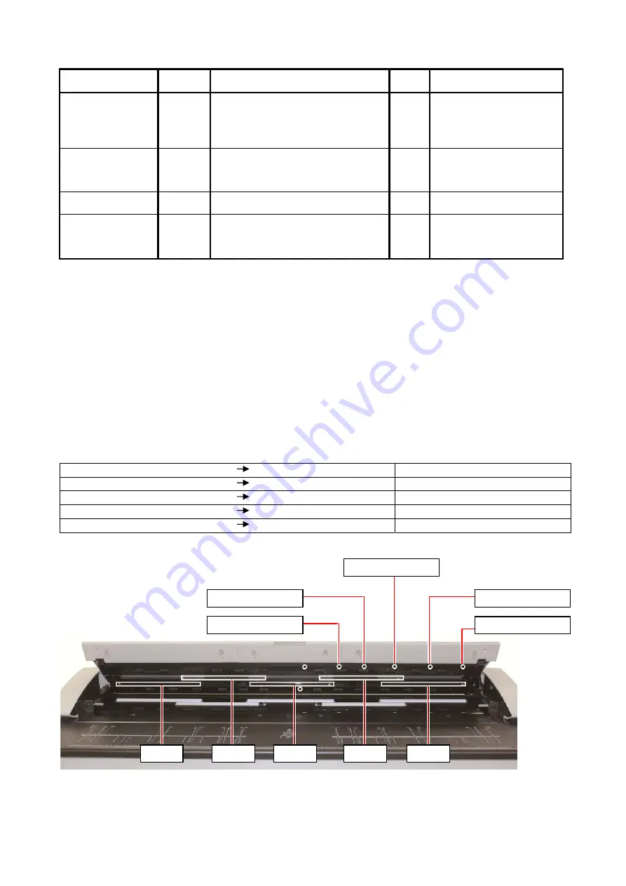
7. 3. 1. 7 Check of Size Sensors
1. Open the Upper Unit when the machine is turned on.
2. Turn off the scanner then turn it on again.
3. Insert a piece of paper under each size sensor to block the sensor light.
4. It is possible to check whether the size sensor is working correctly or not by checking the LED
of concerning CIS.
Size sensor and concerning harness and Main PCB are working correctly if the LED of related
CIS lights
in red
.
If it does not light, any of size sensor, harness and Main PCB has any abnormality.
See the following list for the relationship of size sensor and CIS.
Block the light of Sensor 1 (PH2) LED of CIS 1 lights in red. Sensor 1 (PH2) is working fine.
Block the light of Sensor 2 (PH3) LED of CIS 1 lights in red. Sensor 2 (PH3) is working fine.
Block the light of Sensor 3 (PH4) LED of CIS 1 lights in red. Sensor 3 (PH4) is working fine.
Block the light of Sensor 4 (PH5) LED of CIS 1 lights in red. Sensor 4 (PH5) is working fine.
Block the light of Sensor 5 (PH6) LED of CIS 1 lights in red. Sensor 5 (PH6) is working fine.
CIS 1
CIS 2
CIS 3
CIS 4
CIS 5
Sensor 1 (PH2)
Sensor 2 (PH3)
Sensor 3 (PH4)
Sensor 5 (PH6)
Sensor 4 (PH5)
Summary of Contents for 7170K
Page 1: ...KIP 7170K Service Manual Version A...
Page 46: ...K134sm2e5 2 28 7 Press GUIDES 8 Press Help 9 Press Settings SETTINGS screen appears...
Page 76: ...K134sm2e6 2 58 31 Type 4 with keypad and then click OK on the bottom 32 Click OK on the bottom...
Page 108: ...K134sm4e1 4 4 120V model 230V model 8 7 10 11 12 15 14 13 9...
Page 189: ...K134sm5e4 5 36 64 Press GUIDES 65 Press Help...
Page 384: ...K134sm5eH 5 231 3 Remove both Covers 3 5 6 pulling their sides outward 5 6...
Page 395: ...K134sm5eH 5 242 6 Remove the Blower 9 BL3 BL4 moving as the following photos 9 9...
Page 502: ...K134sm6e1 6 15...
Page 563: ...K134Ksm8e2 8 4 4 Press GUIDES 5 Press Help...
Page 564: ...K134Ksm8e2 8 5 6 Press Setting to indicate SETTINGS page...
Page 594: ...K134Ksm8e2 8 35 2 Press All Items 3 Press Export...
Page 747: ...K134Ksm8e7 8 188 8 9 2 Operation in Error Mask 1 Press Error Mask...
Page 749: ...K134Ksm8e7 8 190 8 9 3 Operation in Jam Mask 1 Press Jam Mask...
Page 750: ...K134Ksm8e7 8 191 2 Select the desired target...
Page 754: ...K134Ksm8e7 8 195 8 11 2 Changing Counter Value 1 Press Total Count 2 Press Edit...
Page 756: ...K134Ksm8e7 8 197 5 Press Edit to enable new value 6 Close the following message pressing OK...
Page 777: ...K134Ksm8e7 8 218 8 19 Communication Reset NOTE This function is not used in the market...
Page 839: ...K134sm8e8 8 280 29 Double click on the row No 15 Stitch Setting 1...
Page 863: ...K134sm9e1 Chapter 9 Appendix...
Page 864: ...KIP 7170 Overall Circuit Diagram USA 120V_KCS...


