background image


3. Circuit Boards - L1500

ORTHOPANTOMOGAPH OP 2D  


    35

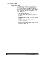
L1500 - Description

L1500 supplies different voltages to most of the circuit 

boards in the unit. L1500 re27V5 and -20V from 

P1910 PFC and regulates these voltages to produce 

the other voltages that the unit requires. 

The CCD sensor r3.3V, +3.3V, +3V, +15V, 

-9.4V, +5V. 

L900 and the 3-phase stepper motor require 24V. 

L1200 and peripheral electronics require a regulated 

5VDC power supply.

P1910 measures mains voltage. This value is converted 

to frequency signal and is then transferred to L1500 

board. On L1500 board the signal is converted to DC 

voltage. This DC voltage is measured by AD-converters 

on L1200 CPU board.

Summary of Contents for ORTHOPANTOMOGAPH OP 2D

Page 1: ...ORTHOPANTOMOGAPH OP 2D Digital Panoramic X ray Unit Service Manual ENGLISH 216143 rev 1 0 805 5058...

Page 2: ......

Page 3: ...s reserved Under the copyright laws the documentation may not be copied photocopied reproduced translated or reduced to any electronic medium or machine readable form in whole or part without the prio...

Page 4: ...IV ORTHOPANTOMOGAPH OP 2D Contents...

Page 5: ...Electrical Safety 2 Caution Electrostatic discharge 3 Warning Explosion hazard 3 Warning Cleaning the unit 3 1 4 Unauthorized Modifications 4 1 5 Disclaimer 4 1 6 Yearly maintenance 5 Exposure switch...

Page 6: ...d motor control 18 Exposure logic 19 Position control 20 Overview of the Imaging Chain 20 2 6 Block diagram 23 2 7 Fuse diagram 24 2 8 Wiring diagrams overview 25 3 Circuit Boards 29 3 1 L900 Display...

Page 7: ...icator LEDs 41 L1600 Test Points 41 3 5 L1700 Connector Board 42 L1700 Location 42 L1700 Field replaceable parts 42 L1700 Description 43 L1700 Indicator LEDs 43 L1700 Test Points 43 L1700 Block Diagra...

Page 8: ...ts 56 3 10 R5100 3 Phase Microstepper Driver 57 R5100 Location 57 R5100 Field replaceable parts 57 R5100 Description 57 R5100 Indicator LEDs 58 R5100 Test Points 58 3 11 CCD Sensor Filter board 59 CCD...

Page 9: ...out of limits 75 Error E7 Opto or r motor failed during r movement 75 Error E8 File system failure 76 Error E10 CCD initialization configuration failure 76 Error E11 CCD power failure 76 Error E12 CCD...

Page 10: ...ator board additional instructions 98 L1700 Connector board additional instructions 98 L1200 CPU board additional instructions 99 L1500 Power Supply board additional instructions 99 L1910 PFC board ad...

Page 11: ...d in it Read the unit s installation manual and familiarize your self with the warnings and precautions listed in it Use only the original spare parts that are provided by the manufacturer when repair...

Page 12: ...ture plate in the collimator is made of lead Pb which is toxic Do not touch it with your bare hands Do not open the tubehead There are no serviceable parts mechanical or electrical inside the tubehead...

Page 13: ...cuit boards use an antistatic wrist wrap which is connected to a ground point through a 1 Mohm current limiting cable For a ground point use water pipes radiators or other ob jects that are known to b...

Page 14: ...ided no compo nents or parts are removed from the unit and no unau thorized adjustments are made to the beam limiting unit or tube housing assembly Never remove or remanufacture any part of the tube h...

Page 15: ...and cable if they are dam aged or do not function correctly mA test WARNING X rays are generated when this test is car ried out PROTECT YOURSELF FROM RADIATION 1 Connect the probe of a DMM to test pin...

Page 16: ...the high voltage parts on the L1800 and P1910 boards 2 Select the kV in s2terminal using the setkv xx command Then set exposure time to 2000 ms us ing command exp refer to section 5 S2terminal and ser...

Page 17: ...tch the unit on activate the T mode test and then take an exposure to check that the motors operate smoothly and without any excessive noise Press the up down keys to check the Z motor vertical carria...

Page 18: ...ing properly Tubehead Make sure that oil is not leaking from the tubehead If the tubehead shows signs of oil leakage replace it Fire risk WARNING Disconnect the unit from the main power supply before...

Page 19: ...ironmentally friendly or hazardous These parts must be disposed of in accordance with all lo cal national and international regulations regarding the disposal of non environmentally friendly or hazard...

Page 20: ...used to take x ray exposures of any other part of the human anatomy The unit can be used to take adult panoramic full width child panoramic reduced width TMJ and bitew ing images The unit can operate...

Page 21: ...assemblies 1 Column 2 Upper shelf 3 Tubehead 4 CCD sensor Tubehead 3 CCD sensor 4 Rotating unit 5 Vertical carriage 6 Emergency stop button Press to stop rotate to release 7 On off switch rear of col...

Page 22: ...GAPH OP 2D 2 Unit Description 1 Head support 2 Midsagittal light 3 Mirror 4 Frankfort light and light positioning knob 5 Focal trough positioning knob 6 Patient support 7 Focal trough light 8 Patient...

Page 23: ...election keys P1 Standard Pan P2 Pediatric Pan P3 TMJ BW Bitewing 6 Patient Size selection keys Child Juvenile Adult Large adult 7 Manual M mode selection key 8 kV and mA selection keys manual mode on...

Page 24: ...14 ORTHOPANTOMOGAPH OP 2D 2 Unit Description 2 3 Unit dimensions...

Page 25: ...in this case it must be attached to the show stand part no 9802666 Refer to the installation manual for the instal lation requirements The motorized carriage is attached to the column and can slide u...

Page 26: ...d to the bot tom of the vertical carriage It comprises handgrips for the patient to hold and the patient support The chin rest supports the patients lower jaw and the two temple supports on the head s...

Page 27: ...to L1800 Generator Board and L1500 Power Supply board which supplies low voltages to all the other circuit boards The power for the AC motor Z Motor comes from an autotransformer that is automatically...

Page 28: ...ols unit PC communications The necessary unit settings and parameters for all the imaging programs are stored in the memory which is also on L1200 Motors and motor control There is one stepper motor a...

Page 29: ...e button is pressed and held down The Generator board receives the correct kV and mA references from the CPU A few milliseconds after the exposure button is pressed Expsw preheat is enabled Preh After...

Page 30: ...his description assumes that the unit is ready to take an exposure Image acquisition is controlled by the image capturing driver which is installed as part of the driver software in the PC connected t...

Page 31: ...bit A D converter The CCD sensor board sends the image data now 12 bits to the CPU board where they are saved on the SDRAM The image information is transferred to the PC via the Ethernet cable After...

Page 32: ...22 ORTHOPANTOMOGAPH OP 2D 2 Unit Description...

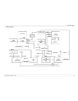
Page 33: ...2 Unit Description ORTHOPANTOMOGAPH OP 2D 23 2 6 Block diagram...

Page 34: ...24 ORTHOPANTOMOGAPH OP 2D 2 Unit Description 2 7 Fuse diagram...

Page 35: ...6 7 0 52 6 7 326 287 6723B 9 6 5 6 5 0 16 6 7 32685 6 7 7 51 76 83 2 1 7 51 7 0 16 7 5 1 1 1 9 9 B B B B 326 287 6723B 9 6 5 51 1 B 7 9 9 51 1 B 7 03 02 8 0 9 7 5 7 5 5 21 26 5 2 23 1 9 36 1 3 3 3 83...

Page 36: ...78 7 78 7 0 0 1 93 0 3 1 78 78 3 1 93 0 1 1 1 35 35 0 3 0 0 3 0 1 5 725 2 5 78 66 0 DVFDGH RDUG 5D 7XEH 0 16 7 5 1 1 3 7XEHKHDG LQWHUIDFH ERDUG 02 1 9 9B 9 1 9 1 02 9 9B 9 1 9 1 02 9 1 9B 9 1 03 02 8...

Page 37: ...W XVHG 63 5 B B 1 63 5 67 57 QRW XVHG 352 0 7 QRW XVHG 728 6 5 1 1 6 96 1 5 5 5 5 5 5 1 1 1 1 9 9 5 8 1 RSWUH 9 9 9 B 1 B 1 B 1 2 5 9 9 1 1 6 53B B 1 6 53B B 1 6 53B B 1 6 53B B 1 VKDUS 352 0 7 QRW XV...

Page 38: ...28 ORTHOPANTOMOGAPH OP 2D 2 Unit Description...

Page 39: ...OP 2D 29 3 Circuit Boards NOTICE An asterisk after a signal name indicates an active low level signal 3 1 L900 Display adapter L900 Location In the rotating unit on the CCD sensor side To access remo...

Page 40: ...h screen interface L900 reads touch screen data and sends it to L1200 CPU board via the SPI interface L1200 CPU board drives the display data throught the L900 board L900 board produces supply voltage...

Page 41: ...t Boards L1200 ORTHOPANTOMOGAPH OP 2D 31 3 2 L1200 CPU Board L1200 Location In rotating unit on the CCD sensor side To access re move the sensor outer cover see section 7 1 L1200 Field replaceable par...

Page 42: ...C connection I O buffers and a 14 bit A D converter The image data are saved in an SDRAM L1200 Indicator LEDs LED Colour Indicates D6 green 5V on D8 green Ethernet signal activity D9 green 10 Base T 1...

Page 43: ...3 Circuit Boards L1200 ORTHOPANTOMOGAPH OP 2D 33 L1200 Block Diagram...

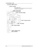
Page 44: ...MOGAPH OP 2D 3 Circuit Boards L1500 3 3 L1500 CCD Power Supply L1500 Location In the rotating unit on the the CCD sensor side To access remove sensor outer cover see section 7 1 L1500 Field replaceabl...

Page 45: ...ther voltages that the unit requires The CCD sensor require 3 3V 3 3V 3V 15V 9 4V 5V L900 and the 3 phase stepper motor require 24V L1200 and peripheral electronics require a regulated 5VDC power supp...

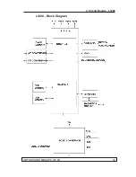
Page 46: ...36 ORTHOPANTOMOGAPH OP 2D 3 Circuit Boards L1500 L1500 Block diagram...

Page 47: ...CD on D12 green 5V on D13 green 5 0V_CCD on D14 green 9 4V_CCD on D16 green 24V on D17 green 3 3V on L1500 Test Points Number Description Value TP1 24V 24V TP5 CCDENA 5V on 0V off TP7 5 0V TP8 5 0V_CC...

Page 48: ...38 ORTHOPANTOMOGAPH OP 2D 3 Circuit Board L1600 3 4 L1600 Z Motor Driver L1600 Location On the upper shelf To access remove shelf upper top cover and the touch protection see section 7 1...

Page 49: ...s on the side of the vertical carriage are used to activate the AC motor Micro switches at the top and bottom of the column monitor the upper and lower positions of the Z move ment Based on the logic...

Page 50: ...40 ORTHOPANTOMOGAPH OP 2D 3 Circuit Board L1600 L1600 Block diagram...

Page 51: ...Emergency stop button is on D5 green SET 100V autotransformer tapping 100V enabled D6 green SET 115V autotransformer tapping 115V enabled D7 green SET 230V autotransformer tapping 230V enabled L1600...

Page 52: ...OMOGAPH OP 2D 3 Circuit Boards L1700 3 5 L1700 Connector Board L1700 Location In the rotating unit on the the CCD sensor side To access remove sensor outer cover see chapter 7 1 L1700 Field replaceabl...

Page 53: ...als to the other boards L1700 receives signals from the tubehead kVfb mafb and tubeheat and scales the voltage swing 0 5V linearly to 1 25V 3 75 V which is the input for the A D converter on the CPU b...

Page 54: ...44 ORTHOPANTOMOGAPH OP 2D 3 Circuit Boards L1700 L1700 Block Diagram...

Page 55: ...erator Board until the capacitors have discharged After switching the unit off wait 10 minutes for the capacitors to discharge When LED H1 goes out the capacitors are discharged L1800 Location In rota...

Page 56: ...e the generator board generates pre heat current to warm up the filament before x rays are switched on and filament current during exposure The Generator board receives kV and mA feedback signals from...

Page 57: ...3 Circuit Boards L1800 ORTHOPANTOMOGAPH OP 2D 47 L1800 Block diagram...

Page 58: ...V FILTERED MAPWM TP3 GND 0V TP4 15V TP5 NOT USED TP6 NOT USED TP7 HVGND 0V TP8 17V TP9 VDD 15V_HVGND TP10 FILTERED KVPWM TP11 mAref Calibrated by the CPU TP12 kVref Counted from value 1V 22kV TP13 NOT...

Page 59: ...t is switched on There is high voltage on the large heat sink on this board when the unit is switched on Do not touch this board until the capacitors have discharged After switching the unit off wait...

Page 60: ...e genera tor board The board also has auxiliary flyback convert er that produces the lower raw voltages for the L1500 power supply board The major features of the board the supply voltages do not depe...

Page 61: ...3 Circuit Boards P1910 ORTHOPANTOMOGAPH OP 2D 51 P1910 Block diagram...

Page 62: ...52 ORTHOPANTOMOGAPH OP 2D 3 Circuit Boards P1910 P1910 Indicator LEDs LED Colour Indicates A5 green 380V A8 green 27V5 A9 green 20V A10 green 17V_HVGND A15 green 15V P1910 Test Points None...

Page 63: ...At the rear of the column near the base part of the main power and interface panel assembly L2000 Field replaceable parts None L2000 Description L2000 serves as an external interface to the outside en...

Page 64: ...54 ORTHOPANTOMOGAPH OP 2D 3 Circuit Boards L2000 L2000 Indicator LEDs None L2000 Test Points None...

Page 65: ...0 Field replaceable parts None L2100 Description L2100 is used to detect the position of the rotating unit L2100 has two optical switches that generate sensor signals ROTSW1 and ROTSW2 according to wh...

Page 66: ...56 ORTHOPANTOMOGAPH OP 2D 3 Circuit Boards L2100 L2100 Indicator LEDs None L2100 Test Points None...

Page 67: ...ead support To ac cess remove the head holder assembly lower protec tion assembly see section 7 1 R5100 Field replaceable parts None R5100 Description R5100 controls the 3 phase stepper motor that dri...

Page 68: ...en 5V on D2 green 24V on R5100 Test Points Number Description Value TP1 GND 0V TP2 VREF 0 97V 0 1V when HICUR 1 1 95V 0 1V when HICUR 0 default value TP3 CLK 5V freq 15kHz TP4 ENA 5V active 0V idle TP...

Page 69: ...board also re quires the sensor to be removed CCD Field replaceable parts None Inside the CCD Sensor there is the CCD Sensor board The board cannot be accessed CCD Description CCD sensor converts X ra...

Page 70: ...quency is between 0 50Hz On TDI frequency is between 100 Hz 1kHz Flashing TDI frequency is between 50 100Hz or above 1kHz Power Supply LEDs Indicate the different voltages required by the CCD sensor T...

Page 71: ...off passive CCD sensor CCD TxD will also be off NOTICE If CCD TxD is off CCD RxD is on and the CCD status LED flashes during and after image capture it indicates that the CCD sensor tried to receive t...

Page 72: ...CD Sensor Filter Filter Field replaceable parts None Filter Description Sensor filter board is a low pass type RF filter board which filters electromagnetic interference EMI from all CCD signal and an...

Page 73: ...error codes H user errors and E system errors When an error code appears on the display the unit will stop working The unit cannot be operated while the er ror code is on the display Clear the error b...

Page 74: ...e An undamaged wire will have close to no resistance 0 ohm a damaged wire will have a high resistance value Make sure that all cables are correctly and securely at tached to their respective connector...

Page 75: ...in fuses 2 They are located below the main power supply cable at the rear of the column The fuse ratings are stated in chapter 2 5 Electrical description Main fuses The on off switch light comes on bu...

Page 76: ...9 3V on when CCDENA is active D10 3 3VD on when CCDENA is active D12 5V must be on D13 5V on when CCDENA is active D14 9 9V on when CCDENA is active D16 24V must be on D17 3 3V must be on Test jumper...

Page 77: ...display CAUSE The emergency switch has been pressed down NOTICE LED D4 ESTOP on on L1600 will come on when the emergency switch is pressed down SOLUTION Turn the emergency switch clockwise to release...

Page 78: ...e is properly attached to its connector on L1600 board CAUSE B The light is faulty SOLUTION B Check if the light works through another Laser output by connecting it to the connector of working light T...

Page 79: ...C Unlikely All the lights are faulty SOLUTION C Replace all the lights they are connected to L1600 Z motor driver and then realign them Refer to the instal lation manual Up down Z motor keys do not wo...

Page 80: ...D5 SET 100V D6 SET 115V D7 SET 230V CAUSE C The side control panel up down keys has failed SOLUTION C If D2 and D3 on L1600 do not come on when the up down keys are pressed it indictes that the side c...

Page 81: ...failed SOLUTION B Replace the exposure switch CAUSE C Faulty cable s between L2000 Interface board and L1600 Z motor driver or between L1600 and L1700 Connector board or between L1700 and L1200 CPU b...

Page 82: ...current are correct Software Check See 5 S2terminal and service functions If the feedback values are not correct use the exp ser vice function to measure and compare the values Re fer to S2terminal an...

Page 83: ...on is not sucessful measure the feedback signals from the L1800 Generator board From the s2terminal select exp Connect a DMM to the TP14 kVfb and TP17 GND on the Generator board and take an exposure T...

Page 84: ...r If the error message reappears after recalibration L1200 is faulty and needs to be replaced See 7 5 Re placing circuit boards Error E4 Tubehead too hot or too cold CAUSE A The tube head has overheat...

Page 85: ...faulty The rotating unit cannot position itself correctly and keeps on rotating until the timeout E 9 stops move ment because L2100 is faulty The rotating unit does not move when the Return key is pre...

Page 86: ...of the fuses on L1500 have blown Check that CCD filter board is mounted correctly and cables are properly connected If the problem still exists replace sensor Error E11 CCD power failure CAUSE Supply...

Page 87: ...error CCD EEPROM CRC test failed CAUSE L1200 CPU failed to read CCD configuration param eters SOLUTION Reboot the unit If the problem persists change the CCD sensor Error E14 Tubehead disconnected CAU...

Page 88: ...00 faulty SOLUTION C Replace cable CAUSE D Cable between L900 and LCD display faulty SOLUTION D Replace cable CAUSE E L900 faulty SOLUTION E Replace L900 CAUSE F LCD display is faulty SOLUTION E Repla...

Page 89: ...up CAUSE The membrane switches on the column are stuck SOLUTION Reboot if problem persists replace the membrane key panel 4 4 Bad quality images Vertical white stripes on the image Probably due to tub...

Page 90: ...tioning If the unit is producing bad quality images first make sure that the user is positioning the patients correctly For information on how to position the patient refer to the User s Manual A badl...

Page 91: ...s 5 In the Command prompt key in cd space and then the path where the S2terminal files are installed e g c s2terminal _________________________________________________________________ cd c s2terminal...

Page 92: ...option to clear it help display info on command help cmd or h cmd imagecalib takes a calibration image for calibrating the DSD ip configure ip address kVcheck test kV mA combinations log service log...

Page 93: ...___________ Information about the selected function will ap pear at the bottom of the list of functions 10 To display information about an individual command key in help cmd where cmd is the command n...

Page 94: ...tion of the procedure which will last up to three min utes During the calibration procedure you will hear the exposure warning signal and calibration values current at the start and calibrated at the...

Page 95: ...P calibration value Use values 8mA 70kV and 1sec FACTORY USE ONLY dc takes dark current image dc dark current Is used to check if the CCD sensor is working Press the Return key to start the check Duri...

Page 96: ...ation when using this function The default exposure time is 1000 ms when exp is keyed in If you wish to have a longer exposure time key in exp and them enter a value for example ______________________...

Page 97: ...ounter when the tubehead is replaced help display info on command help cmd or h cmd Displays the service command list and information about the commands imagecalib takes a calibration image for calibr...

Page 98: ...re logs There are several log options all default display the complete log clear erase all log entries newest display the latest log entry statistics display the log statistics To select one of the lo...

Page 99: ...bugging when the unit displays error E5 motortest run exposure ramp A test drive for the rotation motor The test checks that motor is driven to the correct angle and that it works as specified optotes...

Page 100: ...intgen prints the generator settings Displays the settings that are stored in the configuration memory quit quit service terminal Exits and closes the service terminal reset reboot the unit Reboots th...

Page 101: ...d activates the CCD sensor but the rotating unit does not move It is used to check the beam alignment during unit installation refer to the Installation manual for more information CAUTION Protect you...

Page 102: ...Extract the zip files into a suitable path on your PC 2 Power on the unit to be updated 3 Open the terminal connection 4 Key in command xu rX and press ENTER NOTICE X is the version of the manifest fi...

Page 103: ...7 Replacing parts ORTHOPANTOMOGAPH OP 2D 93 7 Replacing parts 7 1 Removing covers Instruction on how to remove the column covers are in section 7 6 Replacing the z carriage motor...

Page 104: ...The normal installation and alignment tools Replacement parts New tubehead Tubehead label Replacing the tubehead 1 Switch the unit off and disconnect it from the main power supply 2 Remove the tubehea...

Page 105: ...cing parts ORTHOPANTOMOGAPH OP 2D 95 3 Remove the EMC cover 4 screws and then the clear plastic PFC and generator protec tion insulator 3 screws 4 Disconnect all cables and the ground cable from the t...

Page 106: ...he four 4 nuts that hold the tube head to the rotating unit frame and remove the tubehead 7 Attach the new tubehead to the rotating unit frame with the four 4 nuts NOTICE When tightening the tubehead...

Page 107: ...Attach the new tubehead label to the under side of the tubehead side cover 6 Replace the covers 7 3 Replacing the CCD sensor After replacing the CCD sensor realign the unit refer to section 8 Aligning...

Page 108: ...Q057Q3DG01 SW1 off SW2 on NOTICE When L900 and display assemblies are ordered as spareparts they are always preset and tested at the factory The switch information is just for your information L1800 G...

Page 109: ...quired update the FW if required serno setserno Refer to section 5 S2terminal and Service Functions L1500 Power Supply board additional instructions After replacing the board use the s2terminal to rec...

Page 110: ...then the unit removed from the wall and placed on the floor before the z motor is replaced 1 Switch the unit off and disconnect it from the power supply 2 Remove the covers from the bottom of the colu...

Page 111: ...upper self and then disconnect all the cables that connect the rotating unit to the L1600 Z motor board Also disconnect the Ethernet cable and the ground leads 4 CAUTION HEAVY OBJECT THE FOLLOW ING T...

Page 112: ...OLLOW ING TASK REQUIRES TWO PEOPLE Remove the unit from the wall or exhibition stand and lay it on the floor For information on how to do this refer to the installation instructions and follow in reve...

Page 113: ...7 Replacing parts ORTHOPANTOMOGAPH OP 2D 103 7 Carefully slide the column upper front plate off of the column Be careful not to damage the surface finish...

Page 114: ...ety nut to the bottom of the z carriage assembly and then slide the z carriage upwards away from the safety nut 9 Remove the terminal plate from the column assemble 2 screws and then disconnect the mo...

Page 115: ...m of the column assembly and remove the motor 11 Install a new z motor connect all the cables and then replace all part and covers 12 Reattach the unit to the wall or exhibition stand and then reinsta...

Page 116: ...nner or socket wrench 4 mm socket wrench 8 2 Removing the covers 1 Remove the covers from the unit if they have not been removed already 8 3 Checking and Aligning the CCD Sensor 1 Switch the unit and...

Page 117: ...e must be between 0 1 and 2mm from the bottom edge of the image If the beam black line is not in the middle of the CCD aperture the gray area the position of the CCD Sensor must be adjusted to the rig...

Page 118: ...he CCD sensor until the beam is vertical and centered in the middle of the CCD aperture 7 Tighten the nuts after the adjustment 8 4 Adjusting the vertical position of the beam If the bottom edge of th...

Page 119: ...beam downwards turn the height adjustment screw clockwise To move the beam upwards turn the height adjustment screw counter clockwise 3 Tighten the four locking nuts 4 PC Enable image capture on still...

Page 120: ...osition of the collimator 1 Manually rotate the Rotating Unit to the Patient In Out PIO position rotating unit parallel to the front of the upper shelf and the tubehead t h on the right Insert a 4 mm...

Page 121: ...ating unit in position 6 Protect yourself from radiation Press and hold down the exposure switch to take an exposure 7 Compare the two images just taken Use the measuring tools in the dental imag ing...

Page 122: ...the collimator adjusting screw counter clockwise To adjust the collimator loosen the nuts 2 that hold the collimator assembly in position and the adjust the left right position of the collima tor with...

Page 123: ...through the GUI of the unit 2 Make sure that the chin support is in the 0 position and then attach the alignment cone assembly to the chin support 3 Manually rotate the Rotating Unit so that it is par...

Page 124: ...gnment cone will be in the center of the exposed area If you only see the sides of the alignment cone the chin support must be moved to the left or the right To adjust the positon of the chin support...

Page 125: ...he unit 2 Make sure that the chin support is in the 0 position and then attach the alignment cone assembly to the chin support 3 Manually rotate the Rotating Unit to the Patient In Out PIO position Ro...

Page 126: ...the alignment cone the focal trough is not in the correct position and it must be adjusted by moving the rotating unit RU backwards away from col umn or forwards towards the column To adjust the posit...

Page 127: ...left and right hand pins are same with no more than 0 5 mm differ ence the Rotating Unit must be positioned in the forward backward position If the middle ball in the image is too wide turn the adjust...

Page 128: ...igning the Patient Positioning Lasers Refer to the installation manual 8 10 Calibrating the CCD sensor 1 PC Enable image capture 2 PC Select the imagecalib refer to the instal lation manual for inform...

Reviews: