8. Aligning the unit
110
ORTHOPANTOMOGAPH
OP
2D
5.
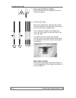
Protect yourself from radiation.
Press and hold down the exposure button to
take and exposure.
6. Check that the beam (black line) is between
0.1 and 2 mm from the bottom edge of the im-
age. If not, redo the adjustment.
8.5 Checking and adjusting the position of the collimator
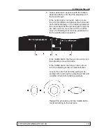
1. Manually rotate the Rotating Unit to the Patient
In/Out (
PIO
) position (rotating unit parallel to
the
front
of the upper shelf and the tubehead
(t/h) on the
right
.
Insert a 4 mm hexagon socket wrench into the
locking hole in the guide pin assembly to hold
the rotating unit in position.
2. Attach the
alignment cone assembly
to the
chin support.
3. PC: Enable image capture for still mode im-
age.
Still mode can be selected using the s2termi-
nal or through the GUI of the unit.
Summary of Contents for ORTHOPANTOMOGAPH OP 2D
Page 2: ......
Page 4: ...IV ORTHOPANTOMOGAPH OP 2D Contents...
Page 24: ...14 ORTHOPANTOMOGAPH OP 2D 2 Unit Description 2 3 Unit dimensions...
Page 32: ...22 ORTHOPANTOMOGAPH OP 2D 2 Unit Description...
Page 33: ...2 Unit Description ORTHOPANTOMOGAPH OP 2D 23 2 6 Block diagram...
Page 34: ...24 ORTHOPANTOMOGAPH OP 2D 2 Unit Description 2 7 Fuse diagram...
Page 38: ...28 ORTHOPANTOMOGAPH OP 2D 2 Unit Description...
Page 43: ...3 Circuit Boards L1200 ORTHOPANTOMOGAPH OP 2D 33 L1200 Block Diagram...
Page 46: ...36 ORTHOPANTOMOGAPH OP 2D 3 Circuit Boards L1500 L1500 Block diagram...
Page 50: ...40 ORTHOPANTOMOGAPH OP 2D 3 Circuit Board L1600 L1600 Block diagram...
Page 54: ...44 ORTHOPANTOMOGAPH OP 2D 3 Circuit Boards L1700 L1700 Block Diagram...
Page 57: ...3 Circuit Boards L1800 ORTHOPANTOMOGAPH OP 2D 47 L1800 Block diagram...
Page 61: ...3 Circuit Boards P1910 ORTHOPANTOMOGAPH OP 2D 51 P1910 Block diagram...


