96
ORTHOPANTOMOGAPH
OP
2D
7. Replacing parts
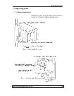
5. Remove the collimator assembly by removing
the two (2) pointed screws.
NOTICE!
It's good to use a pen to mark the corner lo-
cations of the collimator assembly, as shown
in the image. With the markings it's easier to
re-assemble the collimator assembly after the
replacement of tubehead.
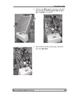
6. Remove the four (4) nuts that hold the
tube-
head
to the
rotating unit frame
and remove
the tubehead.
7. Attach the
new tubehead
to the rotating unit
frame with the four (4) nuts.
NOTICE!
When tightening the tubehead fastening nuts,
prevent the screws from rotating.
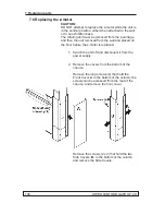
8. Reattach the collimator assembly using the
markings as the indicator for the approximate
location.
NOTICE!
The markings do not guarantee that the unit
alignment remains the same, but they ease the
alignment adjustment work required after the
tubehead replacement.
9. Reconnect all the cables.
Summary of Contents for ORTHOPANTOMOGAPH OP 2D
Page 2: ......
Page 4: ...IV ORTHOPANTOMOGAPH OP 2D Contents...
Page 24: ...14 ORTHOPANTOMOGAPH OP 2D 2 Unit Description 2 3 Unit dimensions...
Page 32: ...22 ORTHOPANTOMOGAPH OP 2D 2 Unit Description...
Page 33: ...2 Unit Description ORTHOPANTOMOGAPH OP 2D 23 2 6 Block diagram...
Page 34: ...24 ORTHOPANTOMOGAPH OP 2D 2 Unit Description 2 7 Fuse diagram...
Page 38: ...28 ORTHOPANTOMOGAPH OP 2D 2 Unit Description...
Page 43: ...3 Circuit Boards L1200 ORTHOPANTOMOGAPH OP 2D 33 L1200 Block Diagram...
Page 46: ...36 ORTHOPANTOMOGAPH OP 2D 3 Circuit Boards L1500 L1500 Block diagram...
Page 50: ...40 ORTHOPANTOMOGAPH OP 2D 3 Circuit Board L1600 L1600 Block diagram...
Page 54: ...44 ORTHOPANTOMOGAPH OP 2D 3 Circuit Boards L1700 L1700 Block Diagram...
Page 57: ...3 Circuit Boards L1800 ORTHOPANTOMOGAPH OP 2D 47 L1800 Block diagram...
Page 61: ...3 Circuit Boards P1910 ORTHOPANTOMOGAPH OP 2D 51 P1910 Block diagram...

