8. Aligning the unit
106
ORTHOPANTOMOGAPH
OP
2D
8. Aligning the unit
After replacing one or more of the following:
tubehead, collimator, CCD sensor, the alignment of
the unit must be checked and adjusted if required.
8.1 Tools required
Normal tools as required for unit installation and
- Ball-pin
tool
- Laser alignment tool
- Alignment cone assembly
- 7 mm spanner or socket wrench
- 4 mm socket wrench
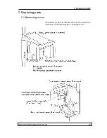
8.2 Removing the covers
1. Remove the covers from the unit if they have
not been removed already.
8.3 Checking and Aligning the CCD Sensor
1. Switch the unit and PC on.
2.
PC:
Open the digital imaging software you are
using and open a patient card where the align-
ment images can be stored.
3.
PC:
Enable image capture for still mode im-
age.
Still mode can be selected using the s2termi-
nal or through the GUI of the unit.
4.
Protect yourself from radiation
.
Press and hold down the exposure button to
take an exposure.
Summary of Contents for ORTHOPANTOMOGAPH OP 2D
Page 2: ......
Page 4: ...IV ORTHOPANTOMOGAPH OP 2D Contents...
Page 24: ...14 ORTHOPANTOMOGAPH OP 2D 2 Unit Description 2 3 Unit dimensions...
Page 32: ...22 ORTHOPANTOMOGAPH OP 2D 2 Unit Description...
Page 33: ...2 Unit Description ORTHOPANTOMOGAPH OP 2D 23 2 6 Block diagram...
Page 34: ...24 ORTHOPANTOMOGAPH OP 2D 2 Unit Description 2 7 Fuse diagram...
Page 38: ...28 ORTHOPANTOMOGAPH OP 2D 2 Unit Description...
Page 43: ...3 Circuit Boards L1200 ORTHOPANTOMOGAPH OP 2D 33 L1200 Block Diagram...
Page 46: ...36 ORTHOPANTOMOGAPH OP 2D 3 Circuit Boards L1500 L1500 Block diagram...
Page 50: ...40 ORTHOPANTOMOGAPH OP 2D 3 Circuit Board L1600 L1600 Block diagram...
Page 54: ...44 ORTHOPANTOMOGAPH OP 2D 3 Circuit Boards L1700 L1700 Block Diagram...
Page 57: ...3 Circuit Boards L1800 ORTHOPANTOMOGAPH OP 2D 47 L1800 Block diagram...
Page 61: ...3 Circuit Boards P1910 ORTHOPANTOMOGAPH OP 2D 51 P1910 Block diagram...

