32
ORTHOPANTOMOGAPH
OP
2D
3. Circuit Boards - L1200
L1200 - Description
The CPU board controls the unit. It controls the rota-
tion and Z movements, the operation of the X-ray tube
and reads the signals from the touch panel. It uses an
embedded microcontroller on an Altera Cyclone FPGA
circuit. The board also has an Ethernet transceiver (for
PC connection), I/O buffers, and a 14-bit A/D converter.
The image data are saved in an SDRAM.
L1200 - Indicator LEDs
LED
Colour Indicates
D6
green
+5V
on
D8
green
Ethernet
signal
activity
D9
green
10-Base-T
(10Mbit/s)
in
use
D10
green
100-Base-T
(100MBit/s)
in
use
D11
green
1000-Base-T
(1000MBit/s)
not
supported
D12
green
Full Duplex mode in use
D13
green
+1.2V
D14
green
+1.8V
D20
green
+5V
D23
green
+3.3V
TEST1
green
Flashing = Core functioning
TEST2
green
Flashing = Firmware functioning
TEST3
green
Flashing = Not currently used
L1200 - Test Points
None
Summary of Contents for ORTHOPANTOMOGAPH OP 2D
Page 2: ......
Page 4: ...IV ORTHOPANTOMOGAPH OP 2D Contents...
Page 24: ...14 ORTHOPANTOMOGAPH OP 2D 2 Unit Description 2 3 Unit dimensions...
Page 32: ...22 ORTHOPANTOMOGAPH OP 2D 2 Unit Description...
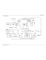
Page 33: ...2 Unit Description ORTHOPANTOMOGAPH OP 2D 23 2 6 Block diagram...
Page 34: ...24 ORTHOPANTOMOGAPH OP 2D 2 Unit Description 2 7 Fuse diagram...
Page 38: ...28 ORTHOPANTOMOGAPH OP 2D 2 Unit Description...
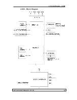
Page 43: ...3 Circuit Boards L1200 ORTHOPANTOMOGAPH OP 2D 33 L1200 Block Diagram...
Page 46: ...36 ORTHOPANTOMOGAPH OP 2D 3 Circuit Boards L1500 L1500 Block diagram...
Page 50: ...40 ORTHOPANTOMOGAPH OP 2D 3 Circuit Board L1600 L1600 Block diagram...
Page 54: ...44 ORTHOPANTOMOGAPH OP 2D 3 Circuit Boards L1700 L1700 Block Diagram...
Page 57: ...3 Circuit Boards L1800 ORTHOPANTOMOGAPH OP 2D 47 L1800 Block diagram...
Page 61: ...3 Circuit Boards P1910 ORTHOPANTOMOGAPH OP 2D 51 P1910 Block diagram...


