8. Aligning the unit
108
ORTHOPANTOMOGAPH
OP
2D
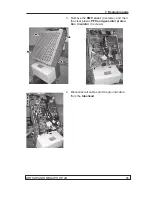
6. Loosen the nuts (4) that hold the CCD sensor
in place and then adjust its position with the
screws (2) on the left-hand side.
Adjust and recheck the position of the CCD
sensor until the beam is vertical and centered
in the middle of the CCD aperture.
7. Tighten the nuts after the adjustment.
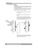
8.4 Adjusting the vertical position of the beam
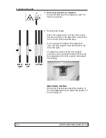
If the bottom edge of the beam (black line) is not
between 0.1 and 2 mm from the bottom edge of
the still mode image, then the height of the beam
must be adjusted. This can be done by adjusting the
height of the collimator.
Screws
Nuts
Summary of Contents for ORTHOPANTOMOGAPH OP 2D
Page 2: ......
Page 4: ...IV ORTHOPANTOMOGAPH OP 2D Contents...
Page 24: ...14 ORTHOPANTOMOGAPH OP 2D 2 Unit Description 2 3 Unit dimensions...
Page 32: ...22 ORTHOPANTOMOGAPH OP 2D 2 Unit Description...
Page 33: ...2 Unit Description ORTHOPANTOMOGAPH OP 2D 23 2 6 Block diagram...
Page 34: ...24 ORTHOPANTOMOGAPH OP 2D 2 Unit Description 2 7 Fuse diagram...
Page 38: ...28 ORTHOPANTOMOGAPH OP 2D 2 Unit Description...
Page 43: ...3 Circuit Boards L1200 ORTHOPANTOMOGAPH OP 2D 33 L1200 Block Diagram...
Page 46: ...36 ORTHOPANTOMOGAPH OP 2D 3 Circuit Boards L1500 L1500 Block diagram...
Page 50: ...40 ORTHOPANTOMOGAPH OP 2D 3 Circuit Board L1600 L1600 Block diagram...
Page 54: ...44 ORTHOPANTOMOGAPH OP 2D 3 Circuit Boards L1700 L1700 Block Diagram...
Page 57: ...3 Circuit Boards L1800 ORTHOPANTOMOGAPH OP 2D 47 L1800 Block diagram...
Page 61: ...3 Circuit Boards P1910 ORTHOPANTOMOGAPH OP 2D 51 P1910 Block diagram...


