8. Aligning the unit
116
ORTHOPANTOMOGAPH
OP
2D
4.
Protect yourself from radiation.
Press and hold down the exposure switch to
take an exposure.
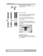
5. Examine the image.
If the focal trough is in the correct position the
top point of the alignment cone will be seen in
the center of the exposed area.
If you only see the sides of the alignment
cone, the focal trough is not in the correct
position and it must be adjusted by moving the
rotating unit (RU) backwards (away from col-
umn) or forwards (towards the column).
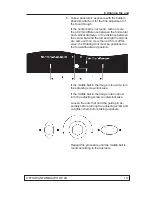
To adjust the positon of the rotating unit loosen
the two nuts that hold the guide pin assembly
in place.
Turn the adjusting screw to move the Rotating
Unit backwards or forwards.
Counter clockwise will move the Rotating Unit
towards the column and clockwise away from
it.
After the adjustment, tighten the nuts holding
the guide pin assembly.
Summary of Contents for ORTHOPANTOMOGAPH OP 2D
Page 2: ......
Page 4: ...IV ORTHOPANTOMOGAPH OP 2D Contents...
Page 24: ...14 ORTHOPANTOMOGAPH OP 2D 2 Unit Description 2 3 Unit dimensions...
Page 32: ...22 ORTHOPANTOMOGAPH OP 2D 2 Unit Description...
Page 33: ...2 Unit Description ORTHOPANTOMOGAPH OP 2D 23 2 6 Block diagram...
Page 34: ...24 ORTHOPANTOMOGAPH OP 2D 2 Unit Description 2 7 Fuse diagram...
Page 38: ...28 ORTHOPANTOMOGAPH OP 2D 2 Unit Description...
Page 43: ...3 Circuit Boards L1200 ORTHOPANTOMOGAPH OP 2D 33 L1200 Block Diagram...
Page 46: ...36 ORTHOPANTOMOGAPH OP 2D 3 Circuit Boards L1500 L1500 Block diagram...
Page 50: ...40 ORTHOPANTOMOGAPH OP 2D 3 Circuit Board L1600 L1600 Block diagram...
Page 54: ...44 ORTHOPANTOMOGAPH OP 2D 3 Circuit Boards L1700 L1700 Block Diagram...
Page 57: ...3 Circuit Boards L1800 ORTHOPANTOMOGAPH OP 2D 47 L1800 Block diagram...
Page 61: ...3 Circuit Boards P1910 ORTHOPANTOMOGAPH OP 2D 51 P1910 Block diagram...


