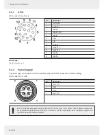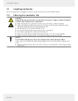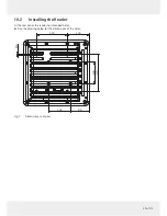
22 of 112
Connections and Displays
9
Connections and Displays
Depending of the device variant, the reader has various connection options. The illustrations below shows an RRU 4000
standard reader with all its connection options. The following chapters provide details of the connections and the pin
assignments of plugs and sockets.
9.1
Front View
1
3
2
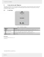
Fig. 5: RRU 4000 – Displays
No.
Name
Function
①
PWR
indicates whether the reader is on; see also
12.4 Reading the PWR LED Indications, p. 36
②
basic LEDs (A1-A4)
indicate if an RF signal is on for antennas 1–4 (default setting)
►
For other functions of the basic LEDs, see
Selecting Functions, p. 79
③
high-end LEDs
1)
see
LED
, p. 78
Related topics
12.4 Reading the PWR LED Indications, p. 36
14.4 LED
, p. 78
1)
Available for RRU 45xx and ARU 35xx


