


Page 34
VIS CAM 300/400 Installation Manual
System Set-Up
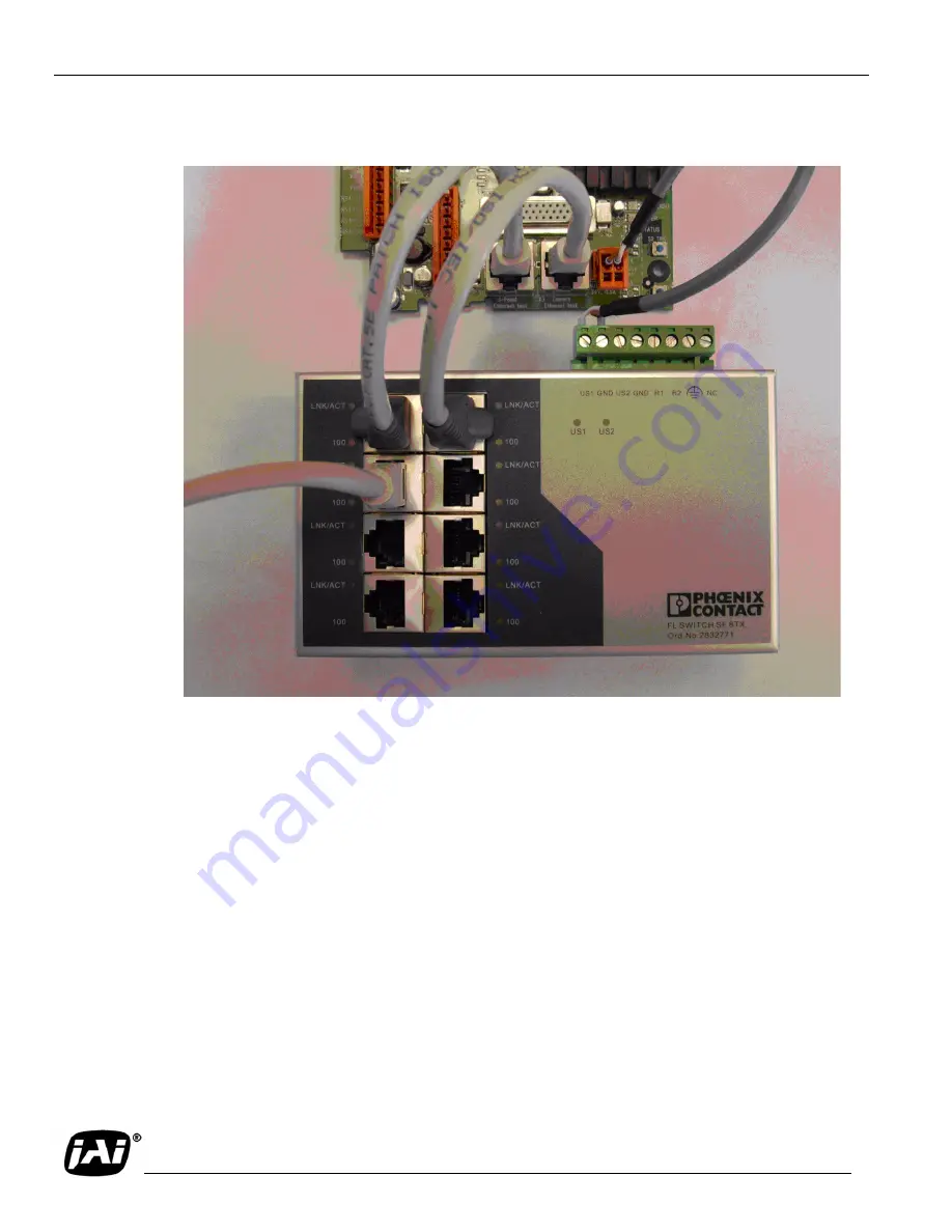
FIGURE 30.
Example of a network connection using a local switch.
The network connection between the Setup computer and the camera can be established using a local
switch. Two separate ports of the Ethernet Switch are connected directly to the I/O board connectors X1
and X3. The Setup computer is then also connected to one of the free ports on the switch. If the switch is
running on 24V dc, the I/O board is capable of supplying up to 0.5A on connector X15 located next to
X1 and X3. The pin marked with #1 on X15 is +24V dc.
4.1.7 Drive and Park the Setup Vehicle Correctly
•
Drive the setup vehicle slowly towards the trigger line through the center of the cameras field of
view in the same manner (heading) as a typical driver would occupy this lane.
Note: This is important, make sure that the vehicle is driven exactly the same way as the
average driver would through the section of roadway being viewed by the camera.
•
Stop the vehicle approximately one foot (0.3 meter) past the trigger line. Make sure that the vehicle
is parked aimed in the same direction as the average driver would point their car if they were driv-
ing through this section of roadway.
•
To help the driver of the vehicle properly aim the car while driving, instruct him (or her) to always
look forward down the road as they would normally. Use a sound to signal the driver when to stop.
Summary of Contents for Vehicle Imaging Subsystem 300
Page 2: ...Page ii Vehicle Imaging Subsystem 300 400 ...
Page 12: ...Page xii List of Tables ...
Page 114: ...Page 102 VIS CAM 300 400 Installation Manual ...
Page 115: ......


