58
EUROCARGO Euro 6
–
CHASSIS INTERVENTIONS
CHASSIS INTERVENTIONS
2.20
REAR UNDER-RUN PROTECTION (RUP)
–
Printed 603.95.747
–
1st Ed. - Base 12/2013
2.20
REAR UNDER-RUN PROTECTION (RUP)
The maximum distance between the rear under-run protection device (RUP = Rear Underrun Protection) and the rear-most
point of the superstructure is 400 mm, less the deformation observed in the approval phase (on average 10 mm).
If the changes on the chassis require the adaptation of the rear overhang, the under-run protection must be placed by performing
the same connection to the chassis as provided in the original version.
In the transformation of the vehicle or in the application of special equipment (e.g. rear tail lifts), it may be necessary to modify the
structure of the under-run. The intervention shall not change the resistance characteristics and the original rigidity.
The compliance of the modified device with standards in force must be demonstrated to the competent authorities by appropriate
documentation or test certificates.
Note
On vehicles with a GVW higher than 14 tons it is necessary to use a rear under-run protection similar to the one of vehicles with
GVW 18 tons, or choose for the opt 4667 provided for vehicles which use a 3rd axis.
2.21
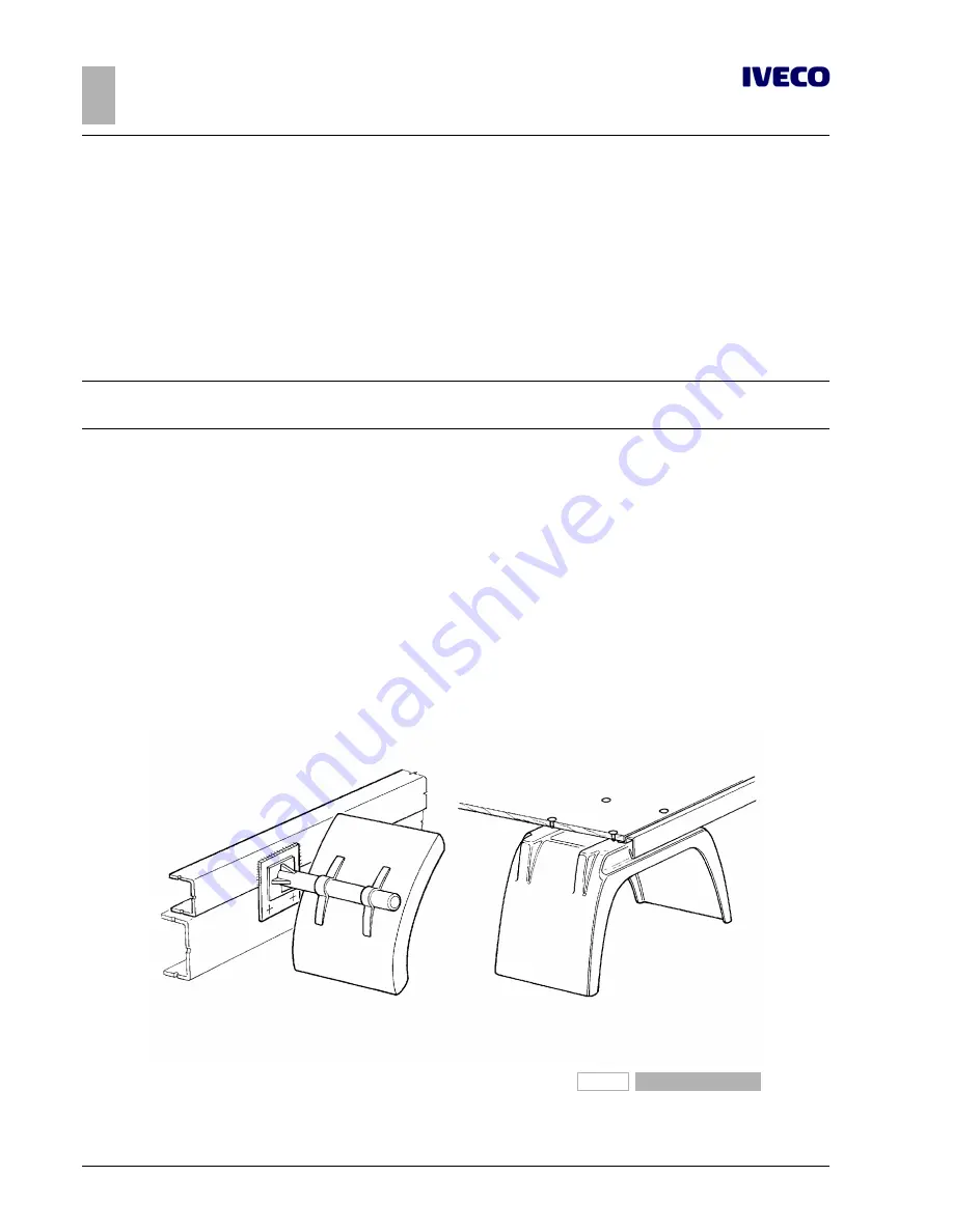
REAR MUD GUARDS AND WHEEL ARCHES
On cab version vehicles without rear fenders, the Bodybuilder must implement solutions equal to those provided by IVECO.
For the realisation of the fenders, the wheel arch boxes and the shaping of the superstructure, keep in mind that:
●
the free shaking of the wheels must be ensured even in the conditions of use with chains; any indications on limit values can be
requested via the Support Service;
●
the width of the fender must be greater than the maximum dimensions occupied by the tyres, within the limits set by the
regulations;
●
the support structure of the fender must have adequate strength and be able to limit the vibrations;
●
the connection can be made
on the vertical rib of the side members of the vehicle (using only the already existing holes) or
directly applied under the superstructure (see Figure 2.31).
The first and the second point are also to be considered in the implementation of wheel arches.
91472
Figure 31
Summary of Contents for EUROCARGO
Page 1: ...EUROCARGO EURO 6 M E D I U M R A N G E BODYBUILDERS INSTRUCTIONS ISSUE 2013 ...
Page 4: ... Printed 603 95 747 Base 12 2013 ...
Page 6: ... Printed 603 95 747 Base 12 2013 ...
Page 8: ... Printed 603 95 747 Base 12 2013 ...
Page 9: ... Printed 603 95 747 Base 12 2013 SECTION 1 GENERAL INFORMATION ...
Page 10: ... Printed 603 95 747 Base 12 2013 ...
Page 29: ... Printed 603 95 747 Base 12 2013 SECTION 2 CHASSIS INTERVENTIONS ...
Page 30: ... Printed 603 95 747 Base 12 2013 ...
Page 91: ... Printed 603 95 747 Base 12 2013 SECTION 3 APPLICATIONS OF SUPERSTRUCTURES ...
Page 92: ... Printed 603 95 747 Base 12 2013 ...
Page 135: ... Printed 603 95 747 Base 12 2013 SECTION 4 POWER TAKE OFFS ...
Page 136: ... Printed 603 95 747 Base 12 2013 ...
Page 138: ...4 EUROCARGO Euro 6 POWER TAKE OFFS POWER TAKE OFFS Printed 603 95 747 1st Ed Base 12 2013 ...
Page 160: ...26 EUROCARGO Euro 6 POWER TAKE OFFS POWER TAKE OFFS Printed 603 95 747 1st Ed Base 12 2013 ...
Page 161: ... Printed 603 95 747 Base 12 2013 SECTION 5 ELECTRONIC SUB SYSTEMS ...
Page 162: ... Printed 603 95 747 Base 12 2013 ...
Page 215: ... Printed 603 95 747 Base 12 2013 SECTION 6 SPECIAL INSTRUCTIONS FOR SCR EXHAUST SYSTEM ...
Page 216: ... Printed 603 95 747 Base 12 2013 ...
Page 226: ... Printed 603 95 747 Base 12 2013 ...


