12
EUROCARGO Euro 6
–
APPLICATIONS OF SUPERSTRUCTURES
APPLICATIONS OF SUPERSTRUCTURES
3.3
CONNECTION BETWEEN CHASSIS AND COUNTER CHASSIS
–
Printed 603.95.747
–
1st Ed. - Base 12/2013
▶
In anchoring the structure to the chassis, welding must not be performed on the vehicle chassis,
nor may holes be put into its wings.
In order to improve the longitudinal and transverse containment of the connection, punctures are permitted on the wings of the
side members only in the rear end of the same, in a section that is no longer than 150 mm and without weakening the anchoring of
any crossbars (see Figure 3.13).
Alternatively, use the connection in Figure 3.12, using the screws that connect the rear crossbar to the frame.
▶
In all other cases, it is absolutely forbidden to put holes in the wings.
Connection characteristics
Elastic connections (see Figures 3.9, 3.10 and 3.11) allow limited movement between the chassis and the counter chassis; These
connections make it possible to consider parallel cooperation of the two resistant sections, where each assumes a share of the
bending moment proportional to its moment of inertia.
In the rigid connections (see Figure 3.12), a single resistant section can be considered for the two profiles, on the condition that the
number and distribution of the connections are such as to withstand the consequent cutting forces.
The possibility of establishing a single resistant section between the chassis and the counter chassis allows you to achieve greater
resistant capacity compared to the connections with brackets or clamps, obtaining the following benefits:
●
lower height of the counter chassis profile to equal bending moment acting on the section;
●
greater bending moment allowed, equal to the dimensions of the counter chassis profile,
●
further increase in the resistance capacity if materials with high mechanical properties are adopted for the counter chassis.
Counter-chassis dimension
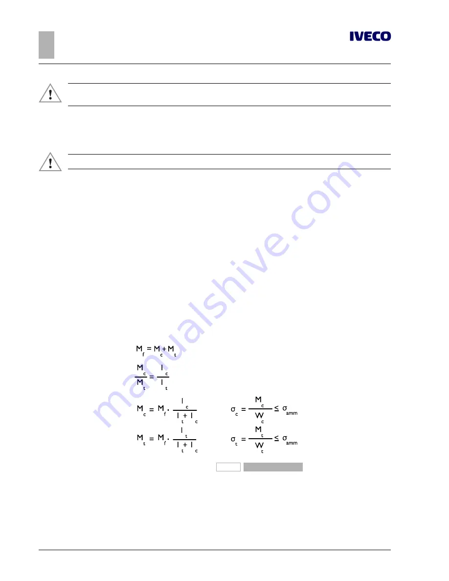
In case of elastic connection between chassis and counter-chassis the bending moment M
f
must be subdivided proportionately
between chassis and counter-chassis at the moments of inertia of the sections:
204635
Figure 8
M
f
= static bending moment generated by the superstructure [Nmm]
M
c
= proportional share of the static bending moment M
f
applied to the counter-chassis [Nmm]
M
t
= proportional share of the static bending moment M
f
applied to the chassis [Nmm]
I
c
= moment of inertia of the section of the counter-chassis [mm
4
]
I
t
= moment of inertia of the section of the chassis [mm
4
]
Summary of Contents for EUROCARGO
Page 1: ...EUROCARGO EURO 6 M E D I U M R A N G E BODYBUILDERS INSTRUCTIONS ISSUE 2013 ...
Page 4: ... Printed 603 95 747 Base 12 2013 ...
Page 6: ... Printed 603 95 747 Base 12 2013 ...
Page 8: ... Printed 603 95 747 Base 12 2013 ...
Page 9: ... Printed 603 95 747 Base 12 2013 SECTION 1 GENERAL INFORMATION ...
Page 10: ... Printed 603 95 747 Base 12 2013 ...
Page 29: ... Printed 603 95 747 Base 12 2013 SECTION 2 CHASSIS INTERVENTIONS ...
Page 30: ... Printed 603 95 747 Base 12 2013 ...
Page 91: ... Printed 603 95 747 Base 12 2013 SECTION 3 APPLICATIONS OF SUPERSTRUCTURES ...
Page 92: ... Printed 603 95 747 Base 12 2013 ...
Page 135: ... Printed 603 95 747 Base 12 2013 SECTION 4 POWER TAKE OFFS ...
Page 136: ... Printed 603 95 747 Base 12 2013 ...
Page 138: ...4 EUROCARGO Euro 6 POWER TAKE OFFS POWER TAKE OFFS Printed 603 95 747 1st Ed Base 12 2013 ...
Page 160: ...26 EUROCARGO Euro 6 POWER TAKE OFFS POWER TAKE OFFS Printed 603 95 747 1st Ed Base 12 2013 ...
Page 161: ... Printed 603 95 747 Base 12 2013 SECTION 5 ELECTRONIC SUB SYSTEMS ...
Page 162: ... Printed 603 95 747 Base 12 2013 ...
Page 215: ... Printed 603 95 747 Base 12 2013 SECTION 6 SPECIAL INSTRUCTIONS FOR SCR EXHAUST SYSTEM ...
Page 216: ... Printed 603 95 747 Base 12 2013 ...
Page 226: ... Printed 603 95 747 Base 12 2013 ...


