38
Using the system
User’s Manual
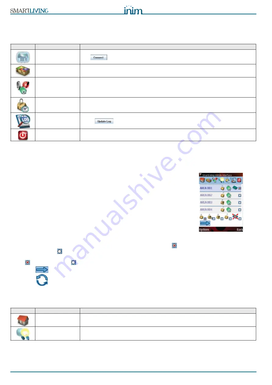
If the connection is successful, the browser will show the first page of the web-
server. The six icons listed below represent the six keys which allow the user to
access the various sections:
5-17-3
Mobile-phone web interface
The web-server interface for mobile-phone devices provides the same functions
the user has access to when operating on the control panel from a remote
computer.
To use this interface, you must connect to the SmartLAN address via a mobile
phone (or similar device), the connection will be diverted automatically to the
respective page. Otherwise, you can connect manually by adding "/mobile/" to
the end of the SmartLAN/G address (e.g. “http://192.168.1.92” becomes
“https://192.168.1.92/mobile/”).
Once access to the web-server has been achieved, the cellphone display will
show:
•
the icons which access the various sections (top of display)
•
the various objects available for selection (centre of display)
•
the icons that represent the functions available for the selected objects
(bottom of display).
All operations must be carried out as follows:
1. Select the desired section from those available at the top of display
2. Select the desired object, from those provided in the centre of display (
:
object selected,
: object not selected)
3. Select the desired function, by means of the icons at the bottom of display
(
: function selected,
: function not selected)
4. Press
to send the command.
5. Press
to update the display.
The difference between the web- interface and the computer interface is that
mobile phone devices do not have access to a virtual keypad, however, they have
two additional sections.
Table 10:
Web-server sections
Icon
Key
Note
Accessing the virtual
keypad
The keypad which is shown is the exact replica of the system keypad.
Use
, to select another type of keypad (if required) from the top right section. At this point,
use the virtual keypad in the same way as you would use the real one (access functions,etc.).
Manage the partitions
The system will allow users to view only information relating to the partitions they control (refer to
paragraph
5-2 Arming and disarming partitions
, paragraph
5-1 Managing alarms
and paragraph
5-5
View
).
Manage zones and
outputs
Using the mouse, select the desired partition. The system will show information regarding the zones
belonging to the selected partition only and will allow you to inhibit/unbypass the zones as required
(refer to paragraph
5-4 Activations
and paragraph
5-5 View
).
The lower section allows you to view the current status of the outputs and activate/deactivate them as
required (refer to paragraph
5-5 View
and paragraph
5-6 Activating/Deactivating outputs
).
View timers
This section allows you to view the status of the 10 control panel timers (refer to paragraph
5-5 View
).
View events log
Press
to initialize and update the control panel events log (refer to paragraph
5-5 View
).
End connection and
exit
The control panel will end the connection and go back to the initial Log-in screen.
Table 11:
Web-server sections
Icon
Key
Note
Scenario activation
This section allows users to activate the scenarios they have access to (refer to paragraph
5-2 Arming
and disarming partitions
).
Outputs management
This section will allow users to view the status of the outputs and also activate/deactivate them (refer to
paragraph
5-5 View
e paragraph
5-6 Activating/Deactivating outputs
)
Summary of Contents for SmartLiving 10100L
Page 45: ...User s Manual 45 Notes...
Page 46: ...46 User s Manual...
Page 47: ...User s Manual 47...


