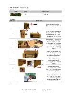
906-0731-04 Rev. B Sept. 2012
Page 47 of 68
8
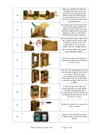
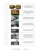
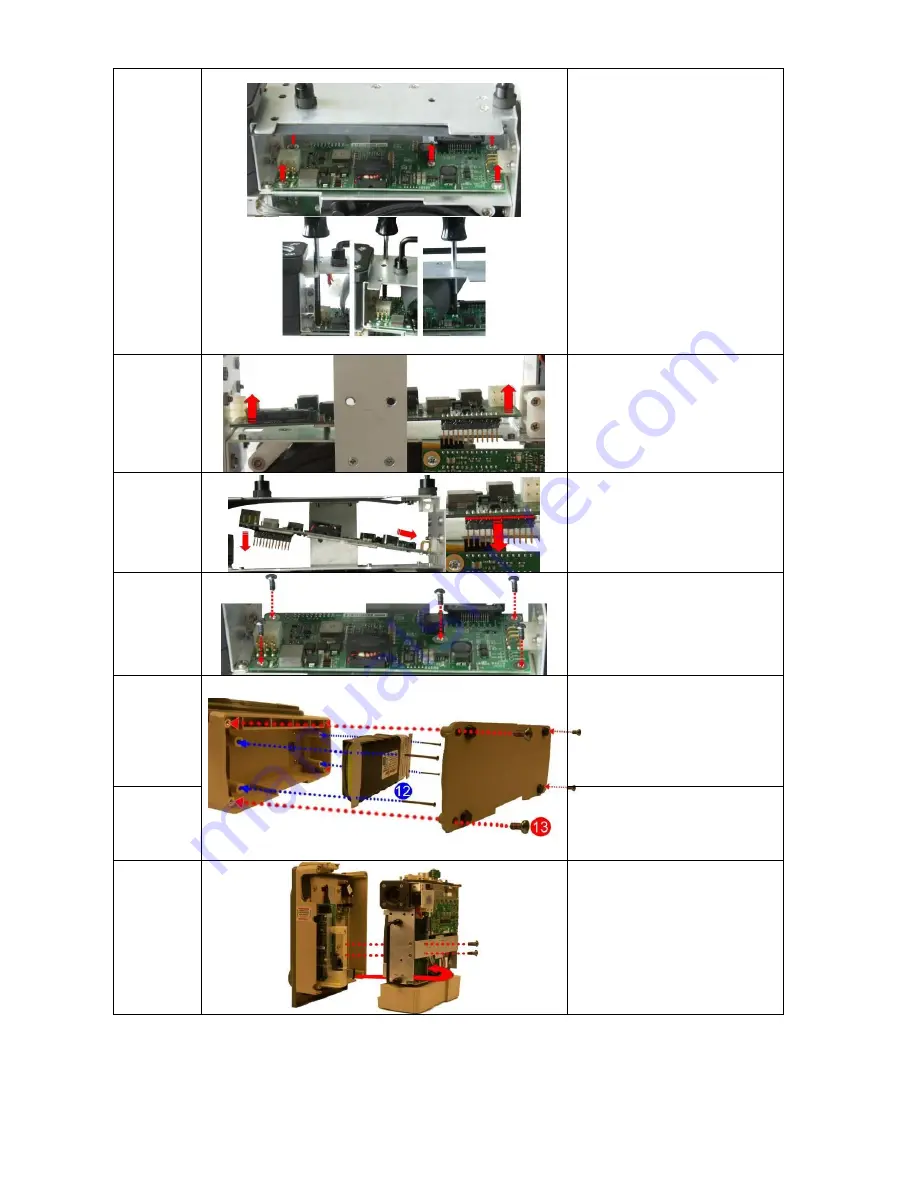
Loosen and remove the(5) 4-40
X 5/16 screws holding the PIM
PCB to the ventilator module.
Position SPO2 Insulator out of
the way (Do Not Fold) and insert
screwdriver through the holes
to aid in removing screws.
9
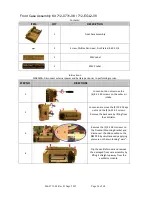
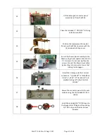
Lift the defective PIM Board out
of the ventilator module.
10
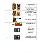
Place the new PIM Board
Unto the vent module (make
sure male header pins are
inserted correctly into the
mating header.
11
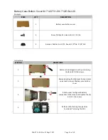
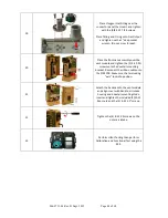
Secure the PIM Board with the
(5) 4-40 x 5/16 screws.
12
Re-assemble the battery by
connecting its cable to the
connector (pull on cable to
insure it is locked in place) then
tightening the (4) 6-32 X 2 ¼
screws.
13
Re-assemble the battery
compartment cover by
tightening the (4) 6-32 X 5/16
screws.
14
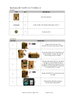
Place the front case assembly
over the vent module and
tighten the (2) 4-40 X ¼ screws
unto the dovetail mounting
bracket. Reconnect the ribbon
cable unto the PIM PCB. Make
sure the two locking “ears” lock
into position.

