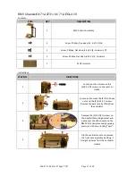
906-0731-04 Rev. B Sept. 2012
Page 22 of 68
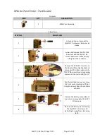
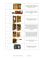
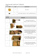
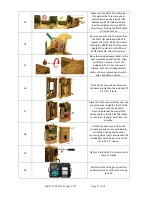
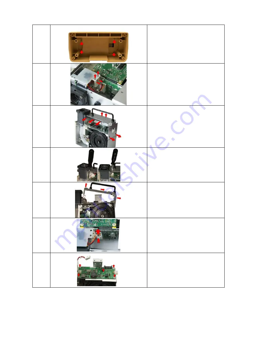
7
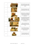
Unscrew the (4) 6-32 X 5/16 Phillips
screws to remove the damaged battery
compartment case.
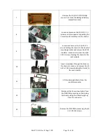
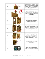
8
Loosen and remove the (2) 4-40 X 1 ¼
Screws and nylon spacers supporting the
Power Input assembly unto the chassis.
9
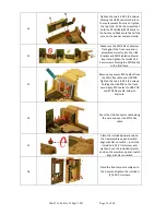
Loosen and remove the (2) 6-32 X ¼
screws holding the chassis to the dovetail
mounting bracket and remove the SPO2
insulator. Loosen and remove the (2) 8-
32 X ¼ screws holding the chassis to the
vent module.
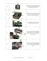
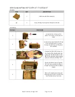
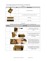
10
Insert screwdriver through the holes on
the chassis to loosen and remove the (2)
6-32 x 5/16 screws holding the chassis to
the vent module.
11
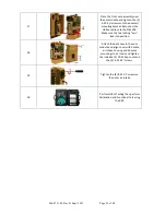
Lift the damaged chassis from the
ventilator module.
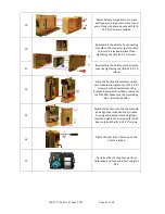
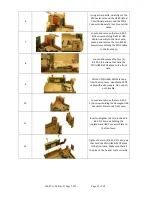
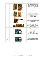
12
Disconnect the Power Input cable from
the PIM PCB by pressing on the locking
latch and pulling the cable straight up
from the connector.
13
Remove the PIM PCB by loosening the (5)
4-40 X 5/16 screws.


