906-0731-04 Rev. B Sept. 2012
Page 56 of 68
5
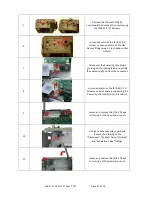
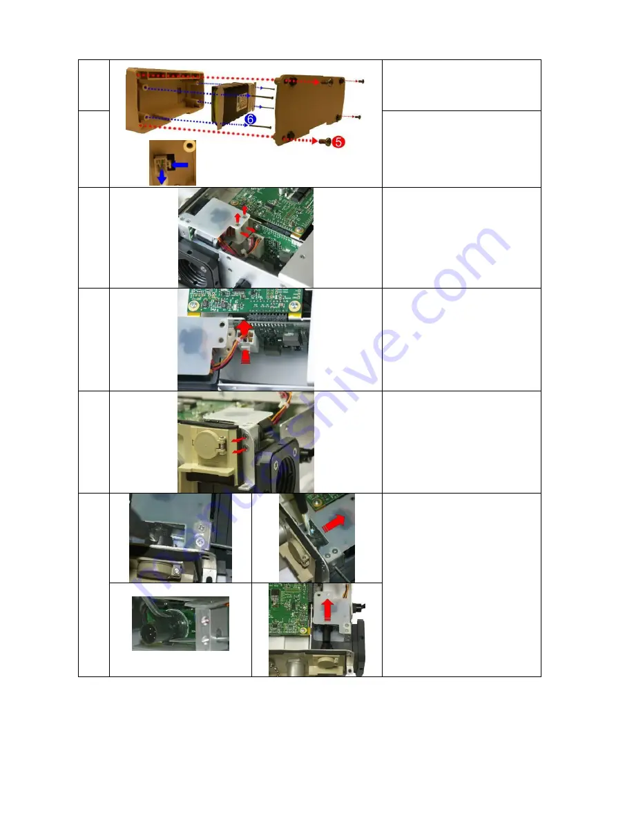
Remove the battery compartment
cover by unscrewing the (4) 6-32 X
5/16 screws.
6
Remove the battery by unscrewing
the (4) 6-32 X 2 ¼ screws and
detaching the plug from its locking
latch.
7
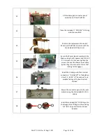
Loosen and remove the (2) 4-40 X
1 ¼ Screws and nylon spacers
supporting the Power Input
assembly unto the chassis.
8
Disconnect the Power Input cable
from the PIM PCB by pressing on
the locking latch and pulling the
cable straight up from the
connector.
9
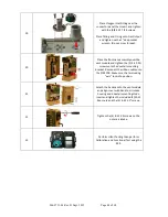
Loosen and remove the (2) 4-40 X
¼ screws holding the Power Input
to the connector panel.
10
Using two small flat blade
screwdrivers, separate the two
locking tabs on the power plug
and pull the power input assembly
away from the connector panel.
Unobstructed view

