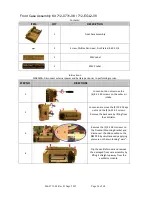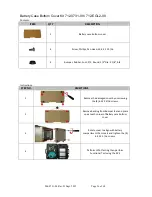
906-0731-04 Rev. B Sept. 2012
Page 39 of 68
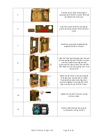
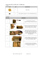
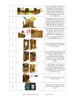
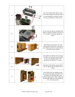
12
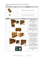
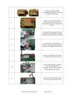
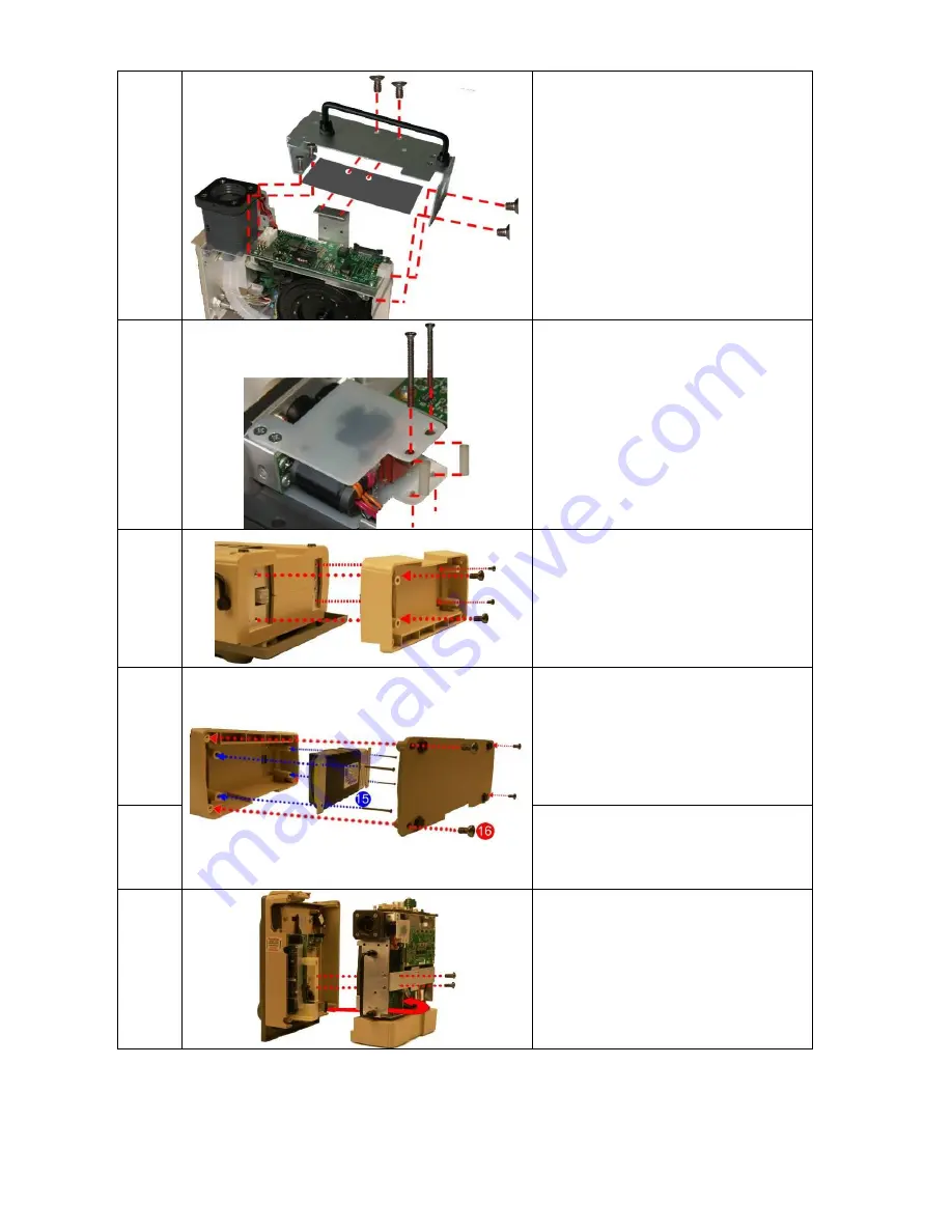
Secure the replacement Chassis to the
vent module using the included (2) 6-32 X
¼ screws with SPO2 insulator, the (2) 8-
32 X ¼ and the (2) 6-32 x 5/16 screws.
13
Secure the Power Input assembly to the
Chassis using the (2) spacers and (2) 4-40
X 1 ¼ screws. Do not over-tighten the
screws.
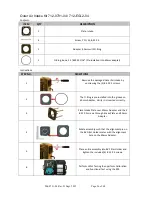
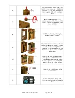
14
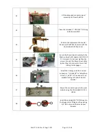
Rotate battery compartment to mate
with upper and lower case cutouts and
press firmly into place. Secure with (4) 6-
32 X 5/16 screws provided.
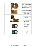
15
Re-assemble the battery by connecting
its cable to the connector (pull on cable
to insure it is locked in place) then
tightening the (4) 6-32 X 2 ¼ screws.
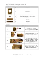
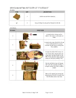
16
Re-assemble the battery compartment
cover by tightening the (4) 6-32 X 5/16
screws.
17
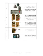
Place the front case assembly over the
vent module and tighten the (2) 4-40 X ¼
screws unto the dovetail mounting
bracket. Reconnect the ribbon cable unto
the PIM PCB. Make sure the two locking
“ears” lock into position.

