906-0731-04 Rev. B Sept. 2012
Page 28 of 68
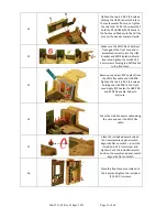
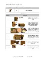
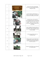
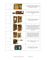
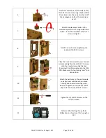
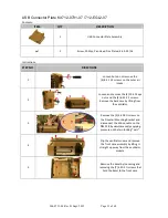
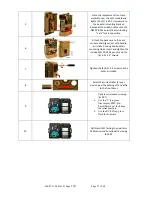
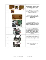
5
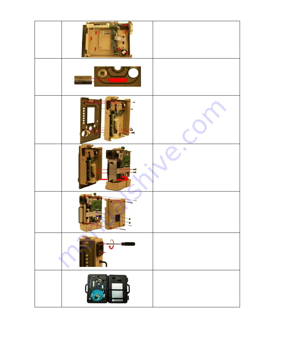
Remove the bezel by loosening and
removing the (7) 4-40 X ¼ screws that hold
the bezel to the front case.
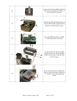
6
Select the correct label for your device,
peel the backing off and affix to the front
bezel.
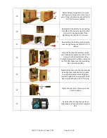
7
Install the new bezel by tightening the
included (7) 4-40 X ¼ screws.
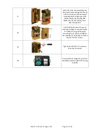
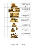
8
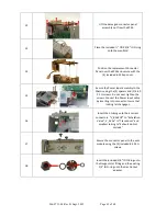
Place the front case assembly over the vent
module and tighten the (2) 4-40 X ¼ screws
unto the dovetail mounting bracket.
Reconnect the ribbon cable unto the PIM
PCB. Make sure the two locking “ears” lock
into position.
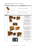
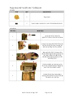
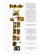
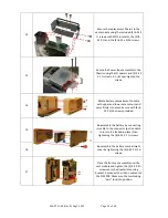
9
Attach the back case to the vent module
and align cover with handle, air intake
housing and dovetail mounting studs.
Insert and tighten the included (2) 10-32
Keps nuts and the (4) 6-32 X 2” screws.
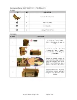
10
Tighten the (4) 8-32 X 3 screws on the
outer air intake.
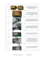
11
Perform HiPot Testing then perform
Functional Test using the RCS.


