906-0731-04 Rev. B Sept. 2012
Page 19 of 68
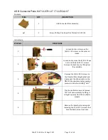
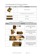
11
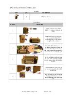
Tighten the two 4-40 X 5/16 screws
holding the USB Connector Plate to
the replacement front case. Tighten
the two (2) 6-32 X 5/16 screws that
hold the CPU/UIM & SPO2 Stack to
the front case. Make sure that all the
pins on the header mate correctly.
12
Make sure the SPO2 Flex Cable lays
flat against the front case and is
assembled correctly into the UIM
Bracket and SPO2 Isolation Shield.
Insert and tighten the two M2.5 X
5mm screws holding the SPO2 cable
to the front case.
13
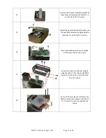
Remove any excess RTV sealant from
the SPO2 flex cable and USB PCB.
Tighten the two 4-40 X 3/16 screws
holding the USB PCB to the front
case. Apply RTV sealant to USB PCB
and SPO2 flex cable. Allow to
dry/cure.
14
Dress the USB Connector cable along
the case and over the SPO2 flex
cable.
15
Place the included power knob on
the new membrane panel switch -
align with flat on switch – insert the
included 6-32 X ¼ set screw and
tighten. Push the included selector
knob on the membrane panel switch
- align with flat on switch .
16
Place the front case assembly on to
the bezel and tighten the included
(7) 4-40 X ¼ screws.


