906-0731-04 Rev. B Sept. 2012
Page 44 of 68
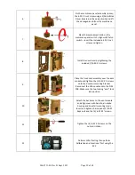
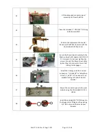
19
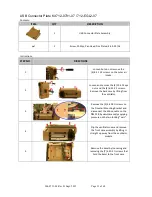
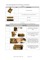
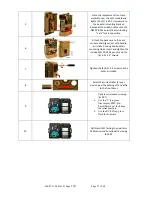
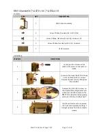
Place Oxygen Inlet Fitting over the
connector panel then insert and tighten
with the (3)8-32 X 7/16 screws.
Place fitting and O-ring unto Gas Output
and tighten with a 1” deep socket
wrench. (Do not cross thread).
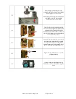
20
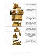
Place the front case assembly over the
vent module and tighten the (2) 4-40 X ¼
screws unto the dovetail mounting
bracket. Reconnect the ribbon cable unto
the PIM PCB. Make sure the two locking
“ears” lock into position.
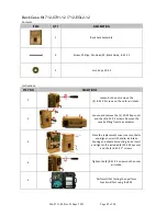
21
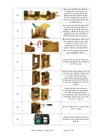
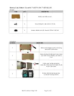
Attach the back case to the vent module
and align cover with handle, air intake
housing and dovetail mounting studs.
Insert and tighten the included (2) 10-32
Keps nuts and the (4) 6-32 X 2” screws.
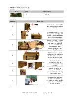
22
Tighten the (4) 8-32 X 3 screws on the
outer air intake.
23
Perform HiPot Testing then perform
Calibration and Functional Test using the
RCS.

