background image

906-0731-04 Rev. B Sept. 2012 

Page 48 of 68 

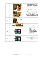
15 


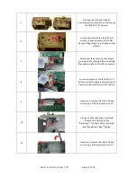
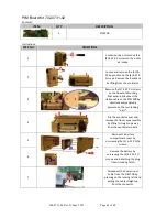
Attach the back case to the vent 

module and align cover with 

handle, air intake housing and 

dovetail mounting studs. Insert 

and tighten the included (2) 10-

32 Keps nuts and the (4) 6-32 X 

2” screws. 

16 


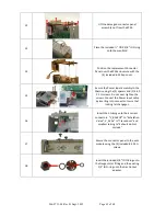
Tighten the (4) 8-32 X 3 screws 

on the outer air intake. 

17 


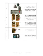
Perform HiPot Testing then 

perform Calibration and 

Functional Test using the RCS. 

Summary of Contents for Uni-Vent 731 Series

Page 1: ...906 0731 04 Rev B Sept 2012 Page 1 of 68 ...

Page 2: ... 16 Replacement Instructions 17 Membrane Panel Kit 712 0731 01 712 EGL2 01 17 SPM Kit 712 0731 02 712 EGL2 02 21 Battery Compartment Kit 712 0731 03 712 EGL2 03 25 Outer Air Intake Kit 712 0731 04 712 EGL2 04 26 Bezel Assembly Kit 712 0731 05 712 EGL2 05 712 AEV1 01 27 Power Knob Kit 712 0731 06 712 EGL2 06 29 USB Connector Plate Kit 712 0731 07 712 EGL2 07 31 Front Case Assembly Kit 712 0731 08 7...

Page 3: ...de ACLS Advanced Cardiac Life Support LPM Liters per Minute ALS Advanced Life Support ml Milliliters ATLS Advanced Trauma Life Support mm Millimeter ACV Assist Control Ventilation NPPV Noninvasive Positive Pressure Ventilation ATPD Atmospheric Temperature and Pressure Dry O2 Oxygen BPM Breaths per Minute Paw Airway Pressure B V Bacterial Viral Filter PEEP Positive End Expiratory Pressure cm H2O Ce...

Page 4: ...trumentation Inc 19 Fairfield Place West Caldwell New Jersey 07006 973 882 1212 or email service impactii com Cautionary Note Prior to servicing this device be aware of the presence of potentially dangerous operating voltages Disconnect power supply and the internal battery prior to performing any service Internal components are susceptible to damage from static discharge All servicing operations ...

Page 5: ...y 90 days Accessories also consumable in usage such as connecting hose and breathing circuits are not warranted DISCLAIMER OF IMPLIED OTHER WARRANTIES THE PRECEDING WARRANTY IS THE EXCLUSIVE WARRANTY AND IMPACT INTRUMENTATION INC MAKES NO OTHER WARRANTY OR REPRESENTATION OF ANY KIND WHATSOEVER EXPRESSED OR IMPLIED WITH RESPECT TO MERCHANTABILITY FITNESS FOR A PARTICULAR PURPOSE OR ANY OTHER MATTER...

Page 6: ...ensure patient electrical isolation connect only to other equipment with electronically isolated circuits WARNING Do not use antistatic or conductive hoses or tubing with this device WARNING Do not connect to an electrical outlet controlled by a wall switch or dimmer WARNING As with all medical equipment carefully route the ventilator circuit hose and tubing patient cabling and external power cabl...

Page 7: ... dyes such as indocyanine green or methylene blue Exposure to excessive illumination such as surgical lamps especially ones with a xenon light source bilirubin lamps fluorescent lights infrared heating lamps or direct sunlight exposure to excessive illumination can be corrected by covering the sensor with a dark or opaque material Excessive patient movement Venous pulsations Placement of a sensor ...

Page 8: ...ns the sensors and connectors are not waterproof Do not sterilize by irradiation steam or ethylene oxide See the cleaning instructions in the directions for reusable Masimo LNCS sensors Do not use damaged patient cables Do not immerse the patient cables in water solvents or cleaning solutions the patient cables are not waterproof Do not sterilize by irradiation steam or ethylene oxide See the clea...

Page 9: ...le or filter is damaged Battery inspection check the battery icon to ensure battery is charging and that the ventilator operates correctly Breathing circuit inspection check on a daily basis the breathing circuit for damage or wear including but not limited to cracking discoloration or disfigurement If there is any sign of physical degradation or the unit is indicating breathing circuit problems r...

Page 10: ...ERVAL Below 68 F 20 C 12 months 68 F to 86 F 20 C to 30 C 6 months 86 F to 104 F 30 C to 40 C 3 months Following periods of extended storage in non controlled environments allow the device sufficient time to stabilize to a temperature within its specified operating range see section entitled BATTERY CARE AND RECHARGING If the device is subject to 6 months of continuous storage non use or longer th...

Page 11: ...ng excessive amounts of water that might enter the unit 10 Never use abrasives or chlorinated hydrocarbon based cleansers when cleaning the ventilator they will damage the plastic and interface lens Removable Foam Filter Replacement Removable Foam Filter The Removable Foam Filter is located on the right side of the ventilator It should be inspected and replaced if needed every 1 000 hours of opera...

Page 12: ...thod and never ship the battery in a completely discharged state CAUTION During continuous uninterrupted use 100 hours it is recommended that the ventilator be disconnected from AC power for 30 seconds to allow the battery to run diagnostics while the battery is discharging NOTE The ventilator continuously monitors the available power sources occasionally a false low priority power alarm can be tr...

Page 13: ...a wide temperature and altitude range to assure display monitoring and triggering accuracy The ventilator also automatically performs an AUTO CAL procedure that affects 3 transducer systems Compressor Flow Oxygen Flow and Airway Pressure The purpose of AUTO CAL is to compensate for small temperature related drifts in the transducer offset zeroing The AUTO CAL is performed at start up during the se...

Page 14: ...by Impact trained and certified biomedical technicians Alternatively 731 series can be sent to an Impact authorized service center for PMC or other service requirements In addition to automating and documenting the PMC process the RCS is also capable of calibrating the device and installing and verifying software upgrades and updates to the 731 series of devices If you would like to return the ven...

Page 15: ...Use the Alarm Category and Service Code matrices listed in Appendix to resolve the problem or to identify the suggested replacement service kit Check on hand availability or order the kit s from Impact then follow the detailed instructions listed to replace the kit Trained repair facilities can contact Impact s technical service department via email service impactii com or by telephone toll free 8...

Page 16: ...712 EGL2 06 USB Connector Plate Kit 712 0731 07 712 EGL2 07 Front Case Assembly Kit 712 0731 08 EMVP 712 AEV1 02 AEV 712 EGL2 08 Battery Case Bottom Cover Kit 712 0731 09 712 EGL2 08 EMV Chassis Kit 712 0731 10 712 EGL2 10 Connector Panel Kit 712 0731 11 712 EGL2 11 Back Case Kit 712 0731 12 712 EGL2 12 PIM Board Kit 702 0731 02 702 0731 02 CPU UIM SPO2 Stack Kit 712 0731 14 712 0731 14 USB Connec...

Page 17: ...ents Instructions STEP NO DIRECTIONS 1 Loosen but do not remove the 4 8 32 X 3 screws on the outer air intake 2 Loosen and remove the 2 10 32 Keps nuts and the 4 6 32 X 2 screws Remove the back case by lifting from the ventilator 3 Remove the 2 4 40 X screws on the Dovetail Mounting Bracket and disconnect the ribbon cable on the PIM PCB by simultaneously applying pressure on the two locking ears I...

Page 18: ...round the SPO2 Connector Be careful not to cut either cable 7 Loosen and remove the two 4 40 X 3 16 screws holding the Mini USB Cable Assembly to the front case Loosen and remove the two M2 5 X 5mm screws holding the SPO2 cable to the front case 8 Loosen and remove the two 2 6 32 X 5 16 screws that hold the CPU UIM SPO2 Stack to the front case 9 Lift the CPU UIM SPO2 Stack up from the front case H...

Page 19: ... X 5mm screws holding the SPO2 cable to the front case 13 Remove any excess RTV sealant from the SPO2 flex cable and USB PCB Tighten the two 4 40 X 3 16 screws holding the USB PCB to the front case Apply RTV sealant to USB PCB and SPO2 flex cable Allow to dry cure 14 Dress the USB Connector cable along the case and over the SPO2 flex cable 15 Place the included power knob on the new membrane panel...

Page 20: ...the PIM PCB Make sure the two locking ears lock into position 18 Attach the back case to the vent module and align cover with handle air intake housing and dovetail mounting studs Insert and tighten the included 2 10 32 Keps nuts and the 4 6 32 X 2 screws 19 Tighten the 4 8 32 X 3 screws on the outer air intake 20 Perform HiPot Testing then perform Calibration and Functional Test using the RCS ...

Page 21: ...3 Remove the 2 4 40 X screws on the Dovetail Mounting Bracket and disconnect the ribbon cable on the PIM PCB by simultaneously applying pressure on the two locking ears 4 Flip the ventilator over and remove the front case assembly by lifting it straight up away from the ventilator module 5 Remove the battery compartment cover by unscrewing the 4 6 32 X 5 16 screws 6 Remove the battery by unscrewin...

Page 22: ...il mounting bracket and remove the SPO2 insulator Loosen and remove the 2 8 32 X screws holding the chassis to the vent module 10 Insert screwdriver through the holes on the chassis to loosen and remove the 2 6 32 x 5 16 screws holding the chassis to the vent module 11 Lift the damaged chassis from the ventilator module 12 Disconnect the Power Input cable from the PIM PCB by pressing on the lockin...

Page 23: ...nto the new SPM assembly by tightening the 2 6 32 X and 2 4 40 X screws 16 Secure the PIM Board to the new SPM with the 5 4 40 x 5 16 screws 17 Secure the chassis to the vent module using the 2 6 32 X screws with SPO2 insulator the 2 8 32 X and the 2 6 32 x 5 16 screws 18 Secure the Power Input assembly to the Chassis using the 2 spacers and 2 4 40 X 1 screws Do not over tighten the screws ...

Page 24: ...tightening the 4 6 32 X 5 16 screws 22 Place the front case assembly over the vent module and tighten the 2 4 40 X screws unto the dovetail mounting bracket Reconnect the ribbon cable unto the PIM PCB Make sure the two locking ears lock into position 23 Attach the back case to the vent module and align cover with handle air intake housing and dovetail mounting studs Insert and tighten the included...

Page 25: ...maged battery compartment case 4 Rotate battery compartment to mate with upper and lower case cutouts and press firmly into place Secure with 4 6 32 X 5 16 screws provided 5 Re assemble the battery by connecting its cable to the connector pull on cable to insure it is locked in place then tightening the 4 6 32 X 2 screws 6 Re assemble the battery compartment cover by tightening the 4 6 32 X 5 16 s...

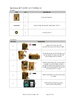
Page 26: ...ver 40mm Adapter and the 4 8 32 X 3 screws through Intake Plate and 40mm Adapter 4 Rotate assembly such that the alignment pin on the BV Filter Holder mates with the alignment hole on the 40mm Adapter 5 Place entire assembly into BV Filter Holder and tighten the included 4 8 32 X 3 screws 6 Perform HiPot Testing then perform Calibration and Functional Test using the RCS ITEM QTY DESCRIPTION 1 Plat...

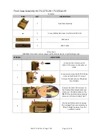
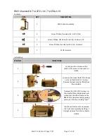
Page 27: ...32 X 2 screws Remove the back case by lifting from the ventilator 3 Remove the 2 4 40 X screws on the Dovetail Mounting Bracket and disconnect the ribbon cable on the PIM PCB by simultaneously applying pressure on the two locking ears 4 Flip the ventilator over and remove the front case assembly by lifting it straight up away from the ventilator module ITEM QTY DESCRIPTION 1 Bezel Assembly 7 Screw...

Page 28: ...front case assembly over the vent module and tighten the 2 4 40 X screws unto the dovetail mounting bracket Reconnect the ribbon cable unto the PIM PCB Make sure the two locking ears lock into position 9 Attach the back case to the vent module and align cover with handle air intake housing and dovetail mounting studs Insert and tighten the included 2 10 32 Keps nuts and the 4 6 32 X 2 screws 10 Ti...

Page 29: ... the ventilator 3 Remove the 2 4 40 X screws on the Dovetail Mounting Bracket and disconnect the ribbon cable on the PIM PCB by simultaneously applying pressure on the two locking ears 4 Flip the ventilator over and remove the front case assembly by lifting it straight up away from the ventilator module 5 Remove the bezel by loosening and removing the 7 4 40 X screws that hold the bezel to the fro...

Page 30: ...g the included 7 4 40 X screws 9 Place the front case assembly over the vent module and tighten the 2 4 40 X screws unto the dovetail mounting bracket Reconnect the ribbon cable unto the PIM PCB Make sure the two locking ears lock into position 10 Attach the back case to the vent module and align cover with handle air intake housing and dovetail mounting studs Insert and tighten the included 2 10 ...

Page 31: ... the ventilator 3 Remove the 2 4 40 X screws on the Dovetail Mounting Bracket and disconnect the ribbon cable on the PIM PCB by simultaneously applying pressure on the two locking ears 4 Flip the ventilator over and remove the front case assembly by lifting it straight up away from the ventilator module 5 Remove the bezel by loosening and removing the 7 4 40 X screws that hold the bezel to the fro...

Page 32: ...osen and remove the two 2 6 32 X 5 16 screws that hold the CPU UIM SPO2 Stack to the front case 9 Lift the CPU UIM SPO2 Stack up from the front case Handle the SPO2 cable with extreme care Do not pull on the cable 10 Loosen and remove the two 4 40 X 5 16 screws holding the damaged USB Connector Plate to the front case 11 Insert and tighten the two included 4 40 X 5 16 screws holding the replacemen...

Page 33: ...sert the included 6 32 X set screw and tighten Push the included selector knob on the membrane panel switch align with flat on switch 16 Place the front case assembly on to the bezel and tighten the included 7 4 40 X screws 17 Place the front case assembly over the vent module and tighten the 2 4 40 X screws unto the dovetail mounting bracket Reconnect the ribbon cable unto the PIM PCB Make sure t...

Page 34: ...e the 2 10 32 Keps nuts and the 4 6 32 X 2 screws Remove the back case by lifting from the ventilator 3 Remove the 2 4 40 X screws on the Dovetail Mounting Bracket and disconnect the ribbon cable on the PIM PCB by simultaneously applying pressure on the two locking ears 4 Flip the ventilator over and remove the damaged front case assembly by lifting it straight up away from the ventilator module I...

Page 35: ...h handle air intake housing and dovetail mounting studs Insert and tighten the included 2 10 32 Keps nuts and the 4 6 32 X 2 screws 7 Tighten the 4 8 32 X 3 screws on the outer air intake 8 Select the correct label for your device peel the backing off and affix to the front bezel 9 Update serial numbers using the RCS a Use the C program files impact EMV bin EmvDLGui exe to change the serial number...

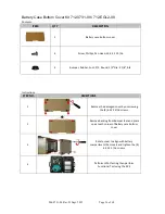
Page 36: ...rews 2 Remove backing from Bumper feet and place one at each corner of Battery case bottom cover 3 Rotate cover to align with battery compartment then insert and tighten the 4 6 32 X 5 16 screws 4 Perform HiPot Testing then perform Functional Test using the RCS ITEM QTY DESCRIPTION 1 Battery case bottom cover 4 Screw Phillips Pan Head SS 6 32 X 5 16 4 Bumper Rubber Foot P S Round 1 2 Dia X 1 8 Blk...

Page 37: ...the ventilator 3 Remove the 2 4 40 X screws on the Dovetail Mounting Bracket and disconnect the ribbon cable on the PIM PCB by simultaneously applying pressure on the two locking ears 4 Flip the ventilator over and remove the front case assembly by lifting it straight up away from the ventilator module ITEM QTY DESCRIPTION 1 EMV Chassis Assembly 2 Screw Phillips Pan Head SS 6 32 X 5 16 2 Screw Phi...

Page 38: ...ase 8 Loosen and remove the 2 4 40 X 1 Screws and nylon spacers supporting the Power Input assembly unto the chassis 9 Loosen and remove the 2 6 32 X screws holding the chassis to the dovetail mounting bracket and remove the SPO2 insulator Loosen and remove the 2 8 32 X screws holding the chassis to the vent module 10 Insert screwdriver through the holes on the chassis to loosen and remove the 2 6...

Page 39: ...with upper and lower case cutouts and press firmly into place Secure with 4 6 32 X 5 16 screws provided 15 Re assemble the battery by connecting its cable to the connector pull on cable to insure it is locked in place then tightening the 4 6 32 X 2 screws 16 Re assemble the battery compartment cover by tightening the 4 6 32 X 5 16 screws 17 Place the front case assembly over the vent module and ti...

Page 40: ...d align cover with handle air intake housing and dovetail mounting studs Insert and tighten the included 2 10 32 Keps nuts and the 4 6 32 X 2 screws 19 Tighten the 4 8 32 X 3 screws on the outer air intake 20 Perform HiPot Testing then perform Calibration and Functional Test using the RCS ...

Page 41: ...2 X 2 screws Remove the back case by lifting from the ventilator 3 Remove the 2 4 40 X screws on the Dovetail Mounting Bracket and disconnect the ribbon cable on the PIM PCB by simultaneously applying pressure on the two locking ears 4 Flip the ventilator over and remove the front case assembly by lifting it straight up away from the ventilator module ITEM QTY DESCRIPTION 1 Connector Panel Assembl...

Page 42: ...nput cable by pressing on the locking latch and pulling the cable straight up from the connector 8 Loosen and remove the 2 4 40 X 1 Screws and nylon spacers supporting the Power Input assembly unto the chassis 9 Loosen and remove the 2 6 32 Keps nuts using a 5 16 open end wrench 10 Using a needle nose pliers carefully remove the 3 tubing on the Transducer Exhaust Do not Occlude and Exhalation Valv...

Page 43: ...ng the 2 spacers and 2 4 40 X 1 screws Do not over tighten the screws Connect the Power Input cable by inserting into connector Insure that locking latch engages 16 Insert the 3 tubing unto their correct connectors V_BACKUP to Exhalation Valve V_ACAL to Transducer and smallest tubing to Exhaust do Not occlude 17 Secure the connector panel to the vent module using the 3 included 8 32 X screws 18 In...

Page 44: ...odule and tighten the 2 4 40 X screws unto the dovetail mounting bracket Reconnect the ribbon cable unto the PIM PCB Make sure the two locking ears lock into position 21 Attach the back case to the vent module and align cover with handle air intake housing and dovetail mounting studs Insert and tighten the included 2 10 32 Keps nuts and the 4 6 32 X 2 screws 22 Tighten the 4 8 32 X 3 screws on the...

Page 45: ... the case by lifting from the ventilator 3 Place the replacement cover over ventilator and align cover with handle air intake housing and dovetail mounting studs Insert and tighten the included 2 10 32 Keps nuts and the 4 6 32 X 2 screws 4 Tighten the 4 8 32 X 3 screws on the outer air intake 5 Perform HiPot Testing then perform Functional Test using the RCS ITEM QTY DESCRIPTION 1 Back Case Assemb...

Page 46: ...isconnect the ribbon cable on the PIM PCB by simultaneously applying pressure on the two locking ears 4 Flip the ventilator over and remove the front case assembly by lifting it straight up away from the ventilator module 5 Remove the battery compartment cover by unscrewing the 4 6 32 X 5 16 screws 6 Remove the battery by unscrewing the 4 6 32 X 2 screws and detaching the plug from its locking lat...

Page 47: ... male header pins are inserted correctly into the mating header 11 Secure the PIM Board with the 5 4 40 x 5 16 screws 12 Re assemble the battery by connecting its cable to the connector pull on cable to insure it is locked in place then tightening the 4 6 32 X 2 screws 13 Re assemble the battery compartment cover by tightening the 4 6 32 X 5 16 screws 14 Place the front case assembly over the vent...

Page 48: ...d align cover with handle air intake housing and dovetail mounting studs Insert and tighten the included 2 10 32 Keps nuts and the 4 6 32 X 2 screws 16 Tighten the 4 8 32 X 3 screws on the outer air intake 17 Perform HiPot Testing then perform Calibration and Functional Test using the RCS ...

Page 49: ...or 3 Remove the 2 4 40 X screws on the Dovetail Mounting Bracket and disconnect the ribbon cable on the PIM PCB by simultaneously applying pressure on the two locking ears 4 Flip the ventilator over and remove the front case assembly by lifting it straight up away from the ventilator module 5 Using a sharp knife carefully cut the RTV sealant around the SPO2 Cable ITEM QTY DESCRIPTION 1 CPU UIM SPO...

Page 50: ...front case 9 Lift the CPU UIM SPO2 Stack up from the front case Handle the SPO2 cable with extreme care Do not pull on the cable 10 Tighten the two 2 6 32 X 5 16 screws that hold the CPU UIM SPO2 Stack to the front case Make sure that all the pins on the header mate correctly 11 Make sure the SPO2 Flex Cable lays flat against the front case and is assembled correctly into the UIM Bracket and SPO2 ...

Page 51: ...mbly over the vent module and tighten the 2 4 40 X screws unto the dovetail mounting bracket Reconnect the ribbon cable unto the PIM PCB Make sure the two locking ears lock into position 16 Attach the back case to the vent module and align cover with handle air intake housing and dovetail mounting studs Insert and tighten the included 2 10 32 Keps nuts and the 4 6 32 X 2 screws 17 Tighten the 4 8 ...

Page 52: ...he Dovetail Mounting Bracket and disconnect the ribbon cable on the PIM PCB by simultaneously applying pressure on the two locking ears 4 Flip the ventilator over and remove the front case assembly by lifting it straight up away from the ventilator module 5 Using a sharp knife carefully cut the RTV sealant around the USB Printed Circuit Board 6 Loosen and remove the two 4 40 X 3 16 screws holding ...

Page 53: ...e tab locks the cable in place 10 Apply RTV Sealant around USB PCB and allow to dry 11 Place the front case assembly over the vent module and tighten the 2 4 40 X screws unto the dovetail mounting bracket Reconnect the ribbon cable unto the PIM PCB Make sure the two locking ears lock into position 12 Attach the back case to the vent module and align cover with handle air intake housing and dovetai...

Page 54: ... by unscrewing with a 1 inch deep socket wrench 2 Place O ring unto underside of outlet fitting 3 Place fitting and O ring unto Gas Output and tighten with a 1 deep socket wrench Do not cross thread 4 Perform HiPot Testing then perform Functional Test using the RCS ITEM QTY DESCRIPTION 1 Fitting Patient Outlet SPM 1 O Ring Neoprene 1 2 ID ...

Page 55: ...lifting from the ventilator 3 Remove the 2 4 40 X screws on the Dovetail Mounting Bracket and disconnect the ribbon cable on the PIM PCB by simultaneously applying pressure on the two locking ears 4 Flip the ventilator over and remove the front case assembly by lifting it straight up away from the ventilator module ITEM QTY DESCRIPTION 1 Power Input Assembly 2 Screw Phillips Flat Head Zinc Plated ...

Page 56: ...nd nylon spacers supporting the Power Input assembly unto the chassis 8 Disconnect the Power Input cable from the PIM PCB by pressing on the locking latch and pulling the cable straight up from the connector 9 Loosen and remove the 2 4 40 X screws holding the Power Input to the connector panel 10 Using two small flat blade screwdrivers separate the two locking tabs on the power plug and pull the p...

Page 57: ...the battery by connecting its cable to the connector pull on cable to insure it is locked in place then tightening the 4 6 32 X 2 screws 15 Re assemble the battery compartment cover by tightening the 4 6 32 X 5 16 screws 16 Place the front case assembly over the vent module and tighten the 2 4 40 X screws unto the dovetail mounting bracket Reconnect the ribbon cable unto the PIM PCB Make sure the ...

Page 58: ...906 0731 04 Rev B Sept 2012 Page 58 of 68 18 Tighten the 4 8 32 X 3 screws on the outer air intake 19 Perform HiPot Testing then perform Calibration and Functional Test using the RCS ...

Page 59: ...s 2 Install the included O Ring into groove on underside of inlet fitting 3 Place Oxygen Inlet Fitting over the ventilators connector panel then insert and tighten the 3 supplied 8 32 X 7 16 screws 4 Perform HiPot Testing then perform Functional Test using the RCS ITEM QTY DESCRIPTION 1 Oxygen Inlet Fitting with Filter Cap and Chain 3 Screw Phillips Flat Head 8 32 X 7 16 ZP 1 O Ring Black Neoprene...

Page 60: ...ck case by lifting from the ventilator 3 Remove the 2 4 40 X screws on the Dovetail Mounting Bracket and disconnect the ribbon cable on the PIM PCB by simultaneously applying pressure on the two locking ears 4 Flip the ventilator over and remove the front case assembly by lifting it straight up away from the ventilator module 5 Remove the bezel from the membrane panel assembly by loosening and rem...

Page 61: ...bracket Reconnect the ribbon cable unto the PIM PCB Make sure the two locking ears lock into position 10 Attach the back case to the vent module and align cover with handle air intake housing and dovetail mounting studs Insert and tighten the included 2 10 32 Keps nuts and the 4 6 32 X 2 screws 11 Tighten the 4 8 32 X 3 screws on the outer air intake 12 For Eagle II ventilators the Selector knob c...

Page 62: ...y to detect presence of high pressure O2 trigger 35 psig clear 45 psig 712 0731 02 O2 Supply Pressure High Fault Failure inability to detect presence of high pressure O2 trigger 80 psig clear 75 psig 712 0731 02 Fresh Gas Intake Fault Failure obstructions of Fresh Gas Emergency Air Intake internal filter dirty clogged pressure drop across filter monitored 712 0731 02 Power Fault Failure failure of...

Page 63: ...l Chain Fault Backup Available communication between compressor controller and SPM is lost 3002 Compressor Fault Compressor Signal Chain Fault Backup Selected communication between compressor controller and SPM is lost 1003 Self Check Failure flow error 20 712 0731 02 1010 O2 Valve Failure O2 Valve Failed Open O2 Valve fails in open position 712 0731 02 1011 O2 Valve Failure O2 Valve Control Fault...

Page 64: ...ay Pressure Sensing Failure communication between airway pressure sensor and SPM is lost 712 0731 02 2053 Suspicious Triggers False Trigger or Bad Baseline airway pressure sensor fails to calibrate during expiratory phase of breath 712 0731 02 1060 Exhalation System Failure Exhalation Valve Failure exhalation control valve fails to operate 712 0731 02 1061 Exhalation System Failure Excessive Airwa...

Page 65: ... breaths 1172 Run Time Self Check Alarm supply voltage to circuitry NG 712 0731 02 2172 Spontaneous Breath Vt High Vt high limit during 2 consecutive spontaneous breaths 1173 Internal Comm Failure communication between EMV and SPM fails Check Cable from PIM board to CPU 702 0731 02 2173 Spontaneous Breath Vt Low Vt low limit during 2 consecutive spontaneous breaths 1174 Self Check Failure failure ...

Page 66: ...on remaining 3431 Low Battery Low Battery With Backup 30 min of battery operation remaining 703 0731 01 3441 External Power Failed External Power High external power trigger 33 VDC clear 30 VDC 702 0731 02 3442 External Power Failed External Power Low 5V external power 11 5V 702 0731 02 3444 External Power Failed external power voltage polarity reversed Use Impact Power supply Only 2450 Battery Fa...

Page 67: ...mmunication Comm Failure CPU unable to communicate with SPM Check Cable from PIM board to CPU 702 0731 02 1473 Internal Comm Failure no valid data sent from SPM Check Cable from PIM board to CPU 702 0731 02 1474 Internal Comm Failure CRC check between EMV and SPM fails Check Cable from PIM board to CPU 702 0731 02 1475 LCD Control Failure CPU unable to control LCD contrast 712 0731 08 1480 SPM Com...

Page 68: ...d 9 Turn the POWER switch ON 10 Set the HiPot tester as follows Voltage 5 00kV Current 50uA Duration 0 5 sec 11 Press the green TEST button The HIGH VOLTAGE ON indicator flashes during the test 12 If the UUT passes the test the tester will beep and display the results 13 If there is a failure the tester will alarm and the red failure indicator will light up To stop the alarm press the red RESET bu...

Reviews: