906-0731-04 Rev. B Sept. 2012
Page 17 of 68
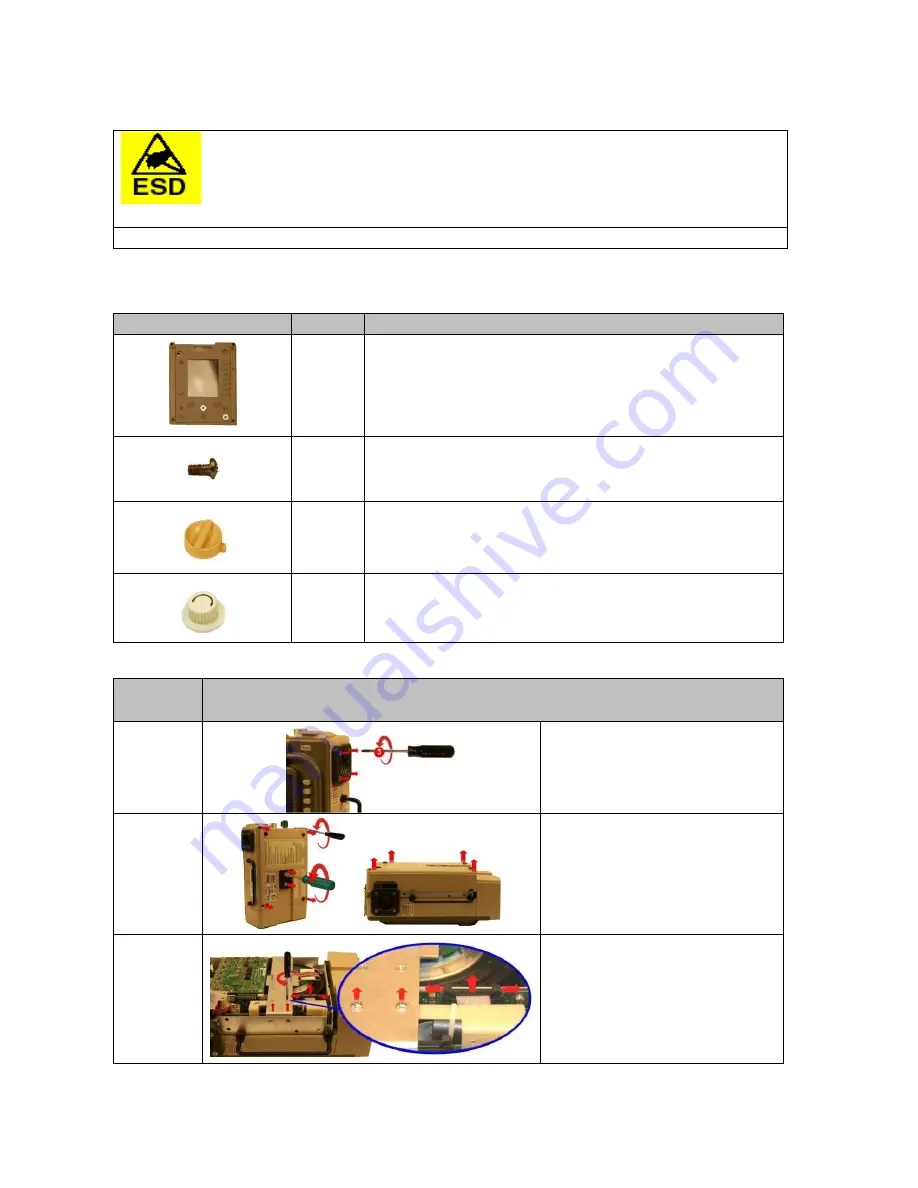
Replacement Instructions
CAUTION!
Internal components are susceptible to damage from static discharge. All servicing
operations MUST be done in an ESD controlled environment.
CAUTION! Disconnect external power and battery pack prior to performing any service.
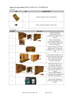
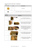
Membrane Panel Kit 712-0731-01 / 712-EGL2-01
Contents:
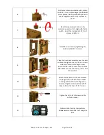
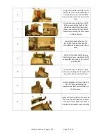
Instructions:
STEP NO.
DIRECTIONS
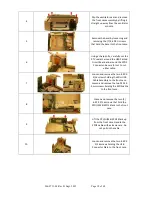
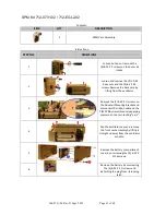
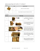
1
Loosen but do not remove the
(4) 8-32 X 3 screws on the outer air
intake.
2
Loosen and remove the (2) 10-32
Keps nuts and the (4) 6-32 X 2
screws. Remove the back case by
lifting from the ventilator.
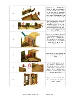
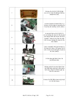
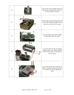
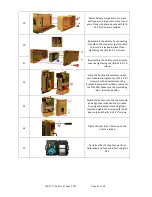
3
Remove the (2) 4-40 X ¼ screws on
the Dovetail Mounting Bracket and
disconnect the ribbon cable on the
PIM PCB by simultaneously applying
pressure on the two locking “ears”.
ITEM
QTY
DESCRIPTION
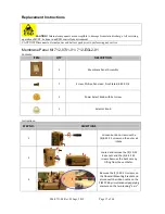
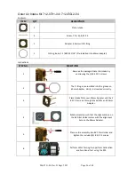
1
Membrane Panel Assembly
7
Screw, Phillips, Pan Head, Zinc Plated, 4-40 X 1/4
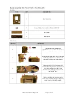
1
Power Select Knob with Set screw
1
Selector Knob


