906-0731-04 Rev. B Sept. 2012
Page 43 of 68
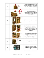
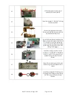
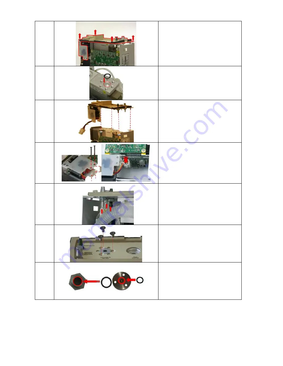
12
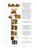
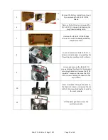
Lift the damaged connector panel
assembly out from the SPM.
13
Place the included ½” OD X 3/8” ID O-ring
onto the manifold.
14
Position the replacement Connector
Panel over the SPM and secure with the
(4) included 6-32 Keps nuts.
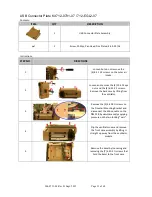
15
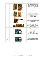
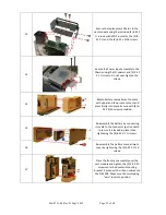
Secure the Power Input assembly to the
Chassis using the (2) spacers and (2) 4-40
X 1 ¼ screws. Do not over-tighten the
screws. Connect the Power Input cable
by inserting into connector. Insure that
locking latch engages.
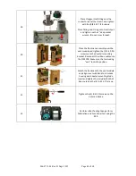
16
Insert the 3 tubing unto their correct
connectors. “V_BACKUP” to “Exhalation
Valve”, V_ACAL” to “Transducer” and
smallest tubing to “Exhaust do Not
occlude”
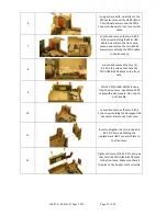
17
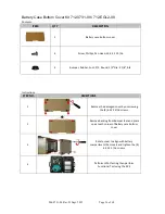
Secure the connector panel to the vent
module using the (3) included 8-32 X ¼
screws.
18
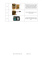
Insert the included 3/8” ID O-Ring unto
the Oxygen Inlet fitting and the existing
1/2” ID O-ring unto the Gas Output
adapter.

