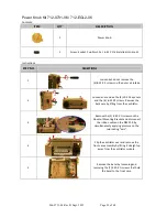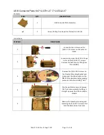
906-0731-04 Rev. B Sept. 2012
Page 30 of 68
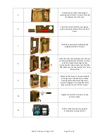
6
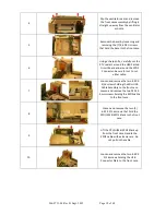
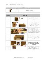
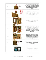
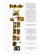
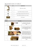
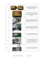
On the membrane panel assembly, loosen
the 6-32 X ¼ set screw using a 1/16 Ball Hex
Driver (located in the power knob) and lift
the damaged knob from the membrane
panel.
7
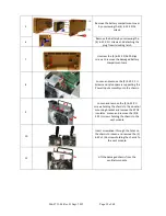
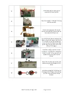
Place the replacement knob on the
membrane panel switch - align with flat on
switch – insert the included 6-32 X ¼ set
screw and tighten.
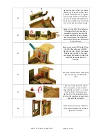
8
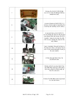
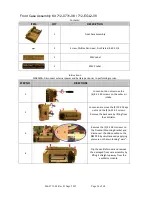
Install the new bezel by tightening the
included (7) 4-40 X ¼ screws.
9
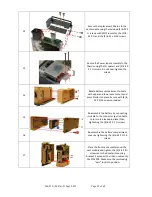
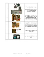
Place the front case assembly over the vent
module and tighten the (2) 4-40 X ¼ screws
unto the dovetail mounting bracket.
Reconnect the ribbon cable unto the PIM
PCB. Make sure the two locking “ears” lock
into position.
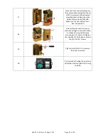
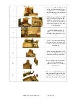
10
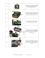
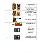
Attach the back case to the vent module
and align cover with handle, air intake
housing and dovetail mounting studs.
Insert and tighten the included (2) 10-32
Keps nuts and the (4) 6-32 X 2” screws.
11
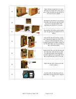
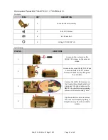
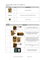
Tighten the (4) 8-32 X 3 screws on the
outer air intake.
12
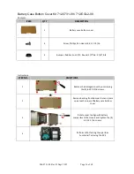
Perform HiPot Testing then perform
Calibration and Functional Test using the
RCS.


