ifm
Supplementary device manual Interface CANopen in the AS-i controllerE
Function
The fieldbus modules
59
5.3.21
The host command channel
The module 19 (
→ page
) contains an extended command channel which can have a length of 5 or
18 words. A PLC with CANopen interface can be used as host system. The commands are always
triggered by the host by a corresponding entry in its output data range. The controllerE responds then
in the input data area of the host system.
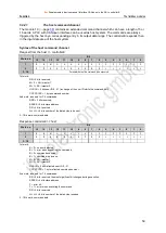
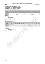
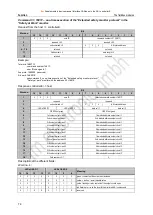
Syntax of the host command channel
Request from the host >> controllerE:
Word no.
Bit
15
14
13
12
11
10
9
8
7
6
5
4
3
2
1
0
1
R
R
M
U
U
U
U
U
C
C
C
C
C
C
C
C
2
R
R
R
S
S
S
S
S
R
R
L
L
L
L
L
L
3...18
Parameter data of the command to be executed
1st word:
RR = 2 bits reserved;
M = 0 = AS-i master 1
M = 1= AS-i master 2
UUUUU = 5 bits user ID 0...31 (a change of the user ID starts the command call)
CCCCCCCC = 1 byte command number
2nd word: reserved for 7.4 commands:
RRR = 3 bits reserved;
SSSSS = 5 bits slave address
RR = 2 bits reserved
LLLLLL = 6 bits number of the data bytes to be sent
3...18th word: command data
Response controllerE >> host:
Word no.
Bit
15
14
13
12
11
10
9
8
7
6
5
4
3
2
1
0
1
E
B
M
U
U
U
U
U
C
C
C
C
C
C
C
C
2
R
R
S
S
S
S
S
F
R
R
L
L
L
L
L
L
3…18
1st word:
E = 0= no error detected
E = 1= error when executing the command;
B = 0= command executed,
B = 1= command in process;
M = 0= AS-i master 1,
M = 1= AS-i master 2
UUUUU = 5 bits reflected user ID 0...31
CCCCCCCC = 1 byte reflected command number
2nd word: reserved for 7.4 commands:
RR = 2 bits reserved, the most significant bit changes during execution;
SSSSS = 5 bits slave address
F = error bit:
F = 1 = error when executing the command
RR = 3 bits reserved
LLLLLL = 6 bits number of the data bytes received
3...18th word: command data


