


ifm
Supplementary device manual Interface CANopen in the AS-i controllerE
Getting started
Overview
12
4
Getting started
4.1
Overview
The chapter General set-
) illustrates the general set-up procedure for the
controllerE devices AC1331 / AC1332 by means of 2 flowcharts. Possible error states and the
corresponding corrective measures are described in additional tables in this chapter.
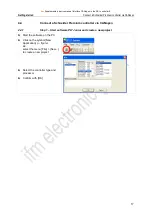
The chapter Connect a Schneider Premium controller via CANopen
) show a configuration
example of a connection between a host PLC Allen Bradley ControlLogix and the controllerE. These
quick instructions presuppose the following:
16 bytes digital input and output data respectively are to be exchanged between the connected
host and the controllerE. Accordingly, the fieldbus modules 1 and 2 are both set to 16 bytes
(→ pages
The node address and the baud rate of the controllerE have been set as defined in the example.
The configuration PC is connected to the host controller.
The controllerE
and the CANopen scanner are switched on and connected to each other via
CANopen.
The following diagram is supposed to give an overview of the system structure and the corresponding
data flow:
controllerE AC1331/32
host PLC
signal transmitter
e.g. inductive proximity
sensor
actuator
e.g. relay or
contactor
data flow of the input signals
data flow of the output signals
AS-i network with digital AS-i slaves