ifm
Supplementary device manual Interface CANopen in the AS-i controllerE
Function
The fieldbus modules
41
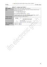
5.3.13
Module 12
– fieldbus data PLC input
Data content
Up to 128 bytes freely definable data
Direction of data
Data from the fieldbus interface to the controllerE
Module settings
Value range
0…128 [bytes]
0
module is deactivated
1…128
module is activated (details → data interpretation)
Data interpretation
Module 12 "fieldbus data PLC input" contains the input data from the controllerE PLC's point of
view, i.e. data which are for example sent by a higher-level PLC to the controllerE. These data
can be accessed via the PLC application program of the controllerE. Access in the user
program is done via the variables
COinData[0]
to
COinData[127]
.
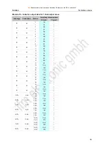
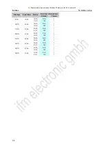
For double-word respresentation in the host PLC the individual bytes are assigned as follows:
PDO
Byte
0
1
2
3
4
5
6
7
x
in-byte 0
in-byte 1
in-byte 2
in-byte 3
in-byte 4
in-byte 5
in-byte 6
in-byte 7
x+1
in-byte 8
in-byte 9
in-byte
10
in-byte
11
in-byte
12
in-byte
13
in-byte
14
in-byte
15
…
…
x+15
in-byte
120
in-byte
121
in-byte
122
in-byte
123
in-byte
124
in-byte
125
in-byte
126
in-byte
127
Example for module 12
Task:
Process data (temperature, pressure, counter values etc.) with a total length of 14 words are to
be transmitted from a higher-level PLC to the controllerE. To which value must module 12 be
set?
Solution:
14 words = 28 bytes
Module 12 must be set to a length of at least 28 bytes in order to transmit all data. In case of
space between the different process data in the transmitted range of the higher-level PLC, this
must also be taken into account for the data length.


