


ifm
Supplementary device manual Interface CANopen in the AS-i controllerE
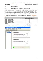
Set-up
Setting and reading of the fieldbus parameters
102
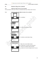
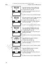
11.
Digital outputs
Master 1 (B)
16
>
Shows that the fieldbus module 6 (digital output
master 1B) with a length of 16 bytes is activated.
► Change the setting with [▲] / [▼].
► Use [OK] to acknowledge the changed setting and
scroll to the next display.
OR:
► Use [ESC] to return to screen 87 [Fieldbus Address]
O
O
K
K
104
E
E
S
S
C
C
12.
Digital inputs
Master 2 (B)
16
>
Shows that the fieldbus module 7 (digital input master
2B) with a length of 16 bytes is activated.
► Change the setting with [▲] / [▼].
► Use [OK] to acknowledge the changed setting and
scroll to the next display.
OR:
► Use [ESC] to return to screen 87 [Fieldbus Address]
O
O
K
K
105
E
E
S
S
C
C
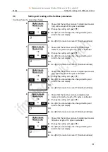
13.
Digital outputs
Master 2 (B)
16
>
Shows that the fieldbus module 8 (digital output
master 2B) with a length of 16 bytes is activated.
► Change the setting with [▲] / [▼].
► Use [OK] to acknowledge the changed setting and
scroll to the next display.
OR:
► Use [ESC] to return to screen 87 [Fieldbus Address]
O
O
K
K
106
E
E
S
S
C
C
14.
Analog
multiplex input
1
>
Shows that the fieldbus module 9 (analogue
multiplexed input) is activated.
► Change the setting with [▲] / [▼].
► Use [OK] to acknowledge the changed setting and
scroll to the next display.
OR:
► Use [ESC] to return to screen 87 [Fieldbus Address]
O
O
K
K
107
E
E
S
S
C
C
15.
Analog
multiplex output
1
>
Shows that the fieldbus module 10 (analogue
multiplexed output) is activated.
► Change the setting with [▲] / [▼].
► Use [OK] to acknowledge the changed setting and
scroll to the next display.
OR:
► Use [ESC] to return to screen 87 [Fieldbus Address]
O
O
K
K
108
E
E
S
S
C
C