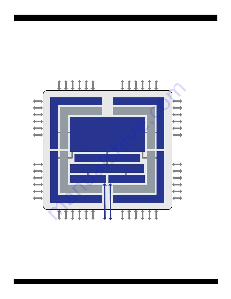
1. Device Overview > Block Diagrams
CPS-1848 User Manual
25
June 2, 2014
Formal Status
This document is confidential and is subject to an NDA.
Integrated Device Technology
1.3
Block Diagrams
shows a high-level overview of the device. Conceptually, the CPS-1848 consists of four quadrants numbered 0 to 3.
Each quadrant consists of 12 lanes that can be mapped to four or five ports. Each quadrant can have combinations of 1x, 2x,
and 4x ports (for more information, see
The ports are connected through a non-blocking switch fabric. The ports and switch fabric support a separate routing path for
maintenance packets which provides register access from any RapidIO port. In addition, the I
2
C Interface and the JTAG 1149.1
Interface also support access to the CPS-1848's registers.
is expanded upon in the following chapters as more
information is provided about the device’s lanes, ports, and switch fabric.
Figure 1: CPS-1848 Block Diagram
provides a summary of the device’s interface signals.
Lanes 0-3, 16-19, 32-35
Lanes 4-7, 20-23, 36-39
Quadrant 0
Quadrant 3
Quadrant 1
Quadrant 2
Ports 0, 4, 8, 12, 16
Ports 3, 7, 11, 15
Lanes 12-15, 28-31, 44-47
Ports 1, 5, 9, 13, 17
Lanes 8-11, 24-27, 40-43
Ports 2, 6, 10, 14
CPS-1848
RapidIO Gen2
Switch Fabric
Event Management and Maintenance
Registers
I
2
C Controller
JTAG Controller


