PCI riser card replacement
To replace the PCI riser card, do the following:
1. Before handling any card, board, or DIMM, be sure to use your electrostatic discharge strap to
minimize static-electric discharge. Refer to “Handling static-sensitive devices” on page 310.
2. If necessary, remove the PCI riser card from the antistatic package.
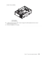
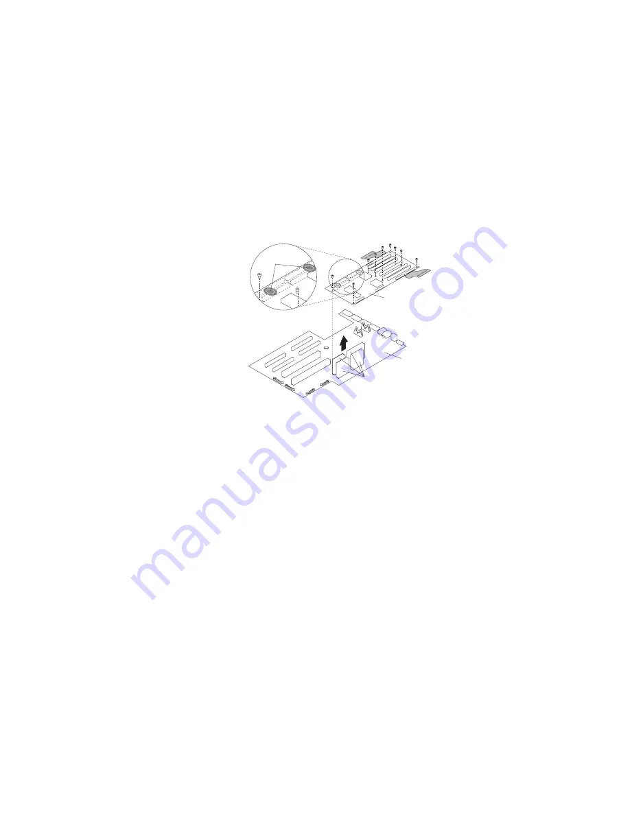
3. Carefully grasp the PCI riser card along two edges, and align the four connectors located on the
bottom side of the PCI riser card with the four standoff connectors located on the CEC backplane.
4. Ensure that you have proper alignment of the PCI-riser-card connectors. Seat the PCI riser card into
the CEC backplane connectors.
a. To perform this procedure requires a considerable amount of force when removing or installing the
PCI riser card from its docking connectors. It is strongly recommended that the system drawer be
removed from the rack.
2
3
4
1
1
PCI riser card
3
CEC backplane connectors to PCI-riser-card connectors
2
CEC backplane
4
“Push” labels
b. To ensure the PCI-riser-card docking connectors are fully seated, using your thumbs, alternately
push down on the two “push” labels that are mounted on the PCI riser card. Push until no more
movement is felt and then push down hard again on both “push” labels. This alternate pushing
technique is allowed only for this card.
Note:
Mounted below the CEC backplane is an aluminum plate. The plate aids in stiffening the
CEC backplane and keeps it from flexing or cracking when the PCI riser card is inserted.
c. If you experience any problem when you boot the system, repeat substep 4, but the second time,
you must push harder.
5. Replace the seven hex-head screws and the two 5.5-mm nuts that secure the PCI riser card to the
CEC backplane and chassis.
Note:
For proper alignment, insert all screws before tightening.
6. Replace the plastic protector on top of the riser card.
7. Reconnect the power, signal, and SCSI cables.
8. Replace the PCI-X hot plug separators
9. Replace all adapters to their proper locations as described in “PCI-X adapter replacement” on
page 325.
10. Reconnect all of the labeled PCI-X adapter cables to their respective PCI-X adapters.
11. Replace the processor card assembly #2 as described in “Processor book insertion” on page 344. If
you removed a processor filler panel, replace the processor filler panel now.
Chapter 11. Removal and replacement procedures
357
Summary of Contents for TotalStorage NAS Gateway 500
Page 1: ...IBM TotalStorage NAS Gateway 500 Service Guide GY27 0418 00 ...
Page 2: ......
Page 3: ...IBM TotalStorage NAS Gateway 500 Service Guide GY27 0418 00 ...
Page 16: ...xiv NAS Gateway 500 Service Guide ...
Page 20: ...xviii NAS Gateway 500 Service Guide ...
Page 36: ...System logic flow Note Not all components are supported 16 NAS Gateway 500 Service Guide ...
Page 52: ...32 NAS Gateway 500 Service Guide ...
Page 58: ...38 NAS Gateway 500 Service Guide ...
Page 112: ...92 NAS Gateway 500 Service Guide ...
Page 266: ...246 NAS Gateway 500 Service Guide ...
Page 326: ...306 NAS Gateway 500 Service Guide ...
Page 353: ...Chapter 11 Removal and replacement procedures 333 ...
Page 392: ...372 NAS Gateway 500 Service Guide ...
Page 402: ...382 NAS Gateway 500 Service Guide ...
Page 412: ...392 NAS Gateway 500 Service Guide ...
Page 440: ...420 NAS Gateway 500 Service Guide ...
Page 446: ...426 NAS Gateway 500 Service Guide ...
Page 448: ...428 NAS Gateway 500 Service Guide ...
Page 466: ...446 NAS Gateway 500 Service Guide ...
Page 469: ......
Page 470: ... Printed in U S A GY27 0418 00 ...
Page 471: ...Spine information IBM TotalStorage NAS Gateway 500 NAS Gateway 500 Service Guide GY27 0418 00 ...


