Chapter 4. Checkpoints
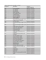
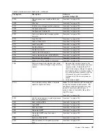
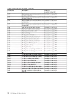
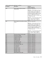
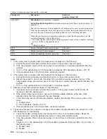
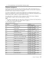
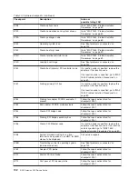
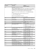
Checkpoints are displayed on the media subsystem operator panel and the virtual terminal while the
system is powering on and going through the initial program load (IPL). This chapter explains the IPL flow
of the system and provides a table that lists checkpoints that you might see in the operator panel on the
ASCII terminal.
IPL flow
The IPL process starts when AC power is connected to the system. The IPL process has the following
phases:
v
Phase 1: Service processor initialization
Phase 1 starts when AC power is connected to the system and ends when OK is displayed in the media
subsystem operator panel. 8xxx checkpoints are displayed during this phase. Several 9xxx codes might
also be displayed.
v
Phase 2: Hardware initialization by the service processor
Phase 2 starts when system power-on is initiated by pressing the power on button on the processor
subsystem operator panel. 9xxx checkpoints are displayed during this time. 91FF, the last checkpoint in
this phase, indicates that the transition to phase 3 is taking place.
v
Phase 3: System firmware initialization
At phase 3, a system processor takes over control. During this phase, checkpoints in the form Exxx are
displayed. E105, the last checkpoint in this phase, indicates that control is being passed to the
operating system boot program.
v
Phase 4: Operating system boot
When the operating system starts to boot, checkpoints in the form 0xxx and 2xxx are displayed. This
phase ends when the operating system login prompt is displayed on the operating system console.
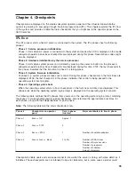
The following table outlines the IPL phases from power-on to the operating system login prompt, matching
the phases to corresponding operator-panel checkpoints. Also listed are the approximate boot times for
each phase, along with their dependencies for each phase.
Note:
The following table lists the major checkpoints only.
Phase #
Checkpoints on operator
panel
Time in phase
(minutes)
Major contributors to time in phase
Phase 1
8xxx => OK
Approx. 1
Phase 2
9xxx => 91FF
3
Phase 3
Exxx => E105
1
Number of bootable adapters
Phase 4
0xxx or 2xxx => blank
2 to 30+
Number of SCSI drives
Number of Async sessions
Number of processors
Number of adapters
Amount of memory
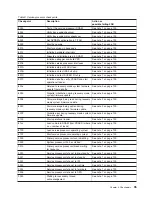
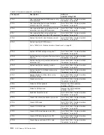
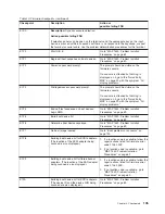
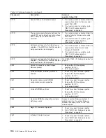
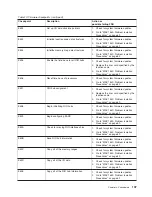
Checkpoints enable users and service personnel to know what the server is doing, with some detail, as it
initializes. These checkpoints are not intended to be error indicators, but in some cases a server could
93
Summary of Contents for TotalStorage NAS Gateway 500
Page 1: ...IBM TotalStorage NAS Gateway 500 Service Guide GY27 0418 00 ...
Page 2: ......
Page 3: ...IBM TotalStorage NAS Gateway 500 Service Guide GY27 0418 00 ...
Page 16: ...xiv NAS Gateway 500 Service Guide ...
Page 20: ...xviii NAS Gateway 500 Service Guide ...
Page 36: ...System logic flow Note Not all components are supported 16 NAS Gateway 500 Service Guide ...
Page 52: ...32 NAS Gateway 500 Service Guide ...
Page 58: ...38 NAS Gateway 500 Service Guide ...
Page 112: ...92 NAS Gateway 500 Service Guide ...
Page 266: ...246 NAS Gateway 500 Service Guide ...
Page 326: ...306 NAS Gateway 500 Service Guide ...
Page 353: ...Chapter 11 Removal and replacement procedures 333 ...
Page 392: ...372 NAS Gateway 500 Service Guide ...
Page 402: ...382 NAS Gateway 500 Service Guide ...
Page 412: ...392 NAS Gateway 500 Service Guide ...
Page 440: ...420 NAS Gateway 500 Service Guide ...
Page 446: ...426 NAS Gateway 500 Service Guide ...
Page 448: ...428 NAS Gateway 500 Service Guide ...
Page 466: ...446 NAS Gateway 500 Service Guide ...
Page 469: ......
Page 470: ... Printed in U S A GY27 0418 00 ...
Page 471: ...Spine information IBM TotalStorage NAS Gateway 500 NAS Gateway 500 Service Guide GY27 0418 00 ...


