CEC backplane replacement
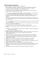
To replace the CEC backplane (system board), do the following:
1. Before handling any card, board, or DIMM, be sure to use your electrostatic discharge strap to
minimize static-electric discharge. Refer to “Handling static-sensitive devices” on page 310.
2. If necessary, remove the CEC backplane from the antistatic package.
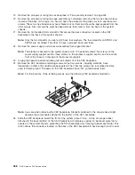
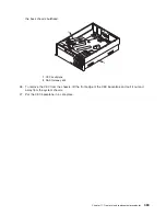
3. Carefully grasp the CEC backplane along two edges and align the retaining screw holes with its
mating screw holes located on the system chassis.
Note:
Use care when replacing the CEC backplane. Standoffs attached to the chassis base might
damage the components attached to the bottom of the CEC backplane.
4. Replace the CEC backplane and slide it toward the back of the system. Ensure that all of the back
connectors located on the CEC backplane are positioned correctly through the back chassis
bulkhead.
5. Replace the retaining screws and standoffs that secure the CEC backplane to the system chassis.
Pay attention to the locations from which you removed the screws and standoffs, returning the correct
type to each location.
Note:
For proper alignment, insert all screws and finger-tighten only. Ensure that the CEC backplane
is not binding.
6. Tighten all CEC backplane retaining screws, starting with the 16 threaded standoffs that secure each
connector to the back of the system chassis.
7. Reconnect all power, signal, and SCSI cables that attach to the CEC backplane.
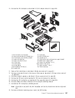
8. Replace the front power supply and processor support bracket. Replace the 13 screws that you
removed.
Note:
Make sure that the operator panel cable is under the standoffs at the bottom of the chassis to
keep it from being pinched.
9. Replace the processor-cooling-fan-cage assembly.
10. Replace the eight screws that secure the processor-cooling-fan-cage assembly to the back chassis,
and then replace the two screws at the base of the cage. You will have to lift the
processor-fan-access cover.
11. Replace the processor cooling fans as described in “Fan assembly replacement” on page 335.
12. Replace the PCI-X adapter cooling-fan-stabilizing cage by installing the two tabs located on the
bottom edge of the cage into their mating slots located on the chassis. Secure the cage to the
chassis with the four screws.
13. Replace the PCI cooling fans as described in “Fan assembly replacement” on page 335.
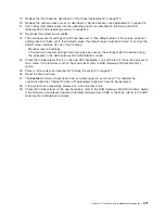
14. Replace the PCI riser card as described in “PCI riser card replacement” on page 357.
15. Replace all PCI-X adapters as described in “PCI-X adapter replacement” on page 325, making sure
that each adapter is returned to its original slot.
16. Replace the processor books and, if applicable, the processor-assembly filler panel.
17. Replace all removed media drives, ensuring that the media drives removed are returned to the same
media bay from which they were removed. Refer to “Media drive replacement” on page 338, if
necessary.
18. Replace the power supplies as described in “Power supply replacement” on page 352.
370
NAS Gateway 500 Service Guide
Summary of Contents for TotalStorage NAS Gateway 500
Page 1: ...IBM TotalStorage NAS Gateway 500 Service Guide GY27 0418 00 ...
Page 2: ......
Page 3: ...IBM TotalStorage NAS Gateway 500 Service Guide GY27 0418 00 ...
Page 16: ...xiv NAS Gateway 500 Service Guide ...
Page 20: ...xviii NAS Gateway 500 Service Guide ...
Page 36: ...System logic flow Note Not all components are supported 16 NAS Gateway 500 Service Guide ...
Page 52: ...32 NAS Gateway 500 Service Guide ...
Page 58: ...38 NAS Gateway 500 Service Guide ...
Page 112: ...92 NAS Gateway 500 Service Guide ...
Page 266: ...246 NAS Gateway 500 Service Guide ...
Page 326: ...306 NAS Gateway 500 Service Guide ...
Page 353: ...Chapter 11 Removal and replacement procedures 333 ...
Page 392: ...372 NAS Gateway 500 Service Guide ...
Page 402: ...382 NAS Gateway 500 Service Guide ...
Page 412: ...392 NAS Gateway 500 Service Guide ...
Page 440: ...420 NAS Gateway 500 Service Guide ...
Page 446: ...426 NAS Gateway 500 Service Guide ...
Page 448: ...428 NAS Gateway 500 Service Guide ...
Page 466: ...446 NAS Gateway 500 Service Guide ...
Page 469: ......
Page 470: ... Printed in U S A GY27 0418 00 ...
Page 471: ...Spine information IBM TotalStorage NAS Gateway 500 NAS Gateway 500 Service Guide GY27 0418 00 ...


