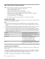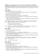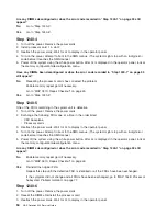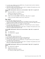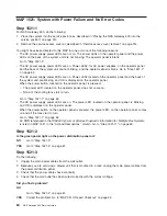
MAP 1521: System with Power Failure and No Error Codes
Step 1521-1
For NAS Gateway 500, do the following:
1. Place the system into the service position as described in “Placing the NAS Gateway 500 into the
service position” on page 312.
2. Remove the service access cover as described in “Service access cover removal” on page 314.
You might have been directed to this MAP for one or more of the following reasons:
v
The AC power supply power LEDs are not on. The power LEDs on the operator panel and the power
LEDs on the back of the system unit are not blinking. The operator panel is blank.
Go to “Step 1521-2”.
v
The AC power supply power LEDs are on. Power LEDs, for AC power supplies, on the operator panel
and the back of the system unit are not blinking, and the operator panel is blank. Go to “Step 1521-7”
on page 62.
v
The AC power supply power LEDs are on. Power LEDs located on the operator panel and the back of
the system unit are blinking, and OK is displayed on the operator panel.
When the power button, located on the operator panel, is pressed:
– The power LED, located on the operator panel, does not come on.
– None of the cooling fans start to turn.
Go to “Step 1521-7” on page 62.
v
The AC power supply power LEDs are on. The power LED, located on the operator panel, is blinking
and OK is displayed on the operator panel.
When the power button on the operator panel is pressed, the power LED, on the operator panel, comes
on and all the fans start to turn.
Go to “Step 1521-7” on page 62.
v
An SRN referenced in the
RS/6000
Eserver
pSeries Diagnostic Information for Multiple Bus Systems
is listed in MAP 1521 in the
″
Actions/Descriptions
″
column. Go to “Step 1521-11” on page 63.
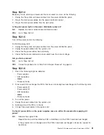
Step 1521-2
Is the green power light on the power distribution panel on?
NO
Go to “Step 1521-3”.
YES
Go to “Step 1521-5” on page 61.
Step 1521-3
Do the following:
1. Unplug the main power cables from the wall outlet.
2. Because you are servicing a drawer unit that is mounted in a rack, unplug the main power cables from
the power distribution panel.
3. Check that the power cables have continuity.
4. Check that the wall outlet has been wired correctly with the correct voltage.
Did you find a problem?
NO
Go to “Step 1521-4” on page 61.
YES
Correct the problem. Go to “MAP 0410: Repair Checkout” on page 45.
60
NAS Gateway 500 Service Guide
Summary of Contents for TotalStorage NAS Gateway 500
Page 1: ...IBM TotalStorage NAS Gateway 500 Service Guide GY27 0418 00 ...
Page 2: ......
Page 3: ...IBM TotalStorage NAS Gateway 500 Service Guide GY27 0418 00 ...
Page 16: ...xiv NAS Gateway 500 Service Guide ...
Page 20: ...xviii NAS Gateway 500 Service Guide ...
Page 36: ...System logic flow Note Not all components are supported 16 NAS Gateway 500 Service Guide ...
Page 52: ...32 NAS Gateway 500 Service Guide ...
Page 58: ...38 NAS Gateway 500 Service Guide ...
Page 112: ...92 NAS Gateway 500 Service Guide ...
Page 266: ...246 NAS Gateway 500 Service Guide ...
Page 326: ...306 NAS Gateway 500 Service Guide ...
Page 353: ...Chapter 11 Removal and replacement procedures 333 ...
Page 392: ...372 NAS Gateway 500 Service Guide ...
Page 402: ...382 NAS Gateway 500 Service Guide ...
Page 412: ...392 NAS Gateway 500 Service Guide ...
Page 440: ...420 NAS Gateway 500 Service Guide ...
Page 446: ...426 NAS Gateway 500 Service Guide ...
Page 448: ...428 NAS Gateway 500 Service Guide ...
Page 466: ...446 NAS Gateway 500 Service Guide ...
Page 469: ......
Page 470: ... Printed in U S A GY27 0418 00 ...
Page 471: ...Spine information IBM TotalStorage NAS Gateway 500 NAS Gateway 500 Service Guide GY27 0418 00 ...

