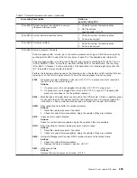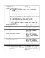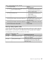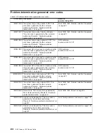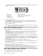
The following figure shows the operator panel and the locations of operator panel components that are
referred to in this procedure.
2
9
8
7
OK
6
1
3 4
5
R
1
Power-on button
6
Operator panel display
2
Power LED
7
(FS1) front serial connector (RJ-48 connector)
3
Attention LED
8
Service processor reset switch (pinhole)
4
SCSI port activity
9
System reset button
5
Ethernet port activity
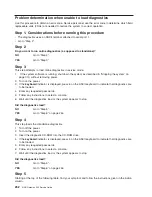
4. Turn on the system unit power.
5. After the
keyboard
POST indicator is displayed on the ASCII terminal and before the last POST
indicator (
speaker
) is displayed, press the numeric 6 key on the ASCII terminal to initiate a service
mode boot using the customized service mode boot list.
6. Enter any requested password.
Note:
If you cannot load the diagnostics to the point when the
DIAGNOSTIC OPERATING INSTRUCTIONS
is
displayed, call your support center for assistance.
Step 3. Run the verification procedure
When the Diagnostic Operating Instructions are displayed, do the following to run system verification:
1. Press
Enter
.
2. If the terminal type has not been defined, the diagnostics prompt you to define your terminal by using
the
Initialize Terminal
option on the Function Selection menu to initialize the operating system
environment before you can continue with the diagnostics.
3. If you want to do a general checkout, with minimal operator action, select the
Diagnostic Routines
option on the Function Selection menu.
If you want to do a more complete checkout, including the use of customer-supplied wrap plugs, select
the
Advanced Diagnostics
option on the Function Selection menu. The advanced diagnostics are
primarily for the service representative; the diagnostics might instruct you to install wrap plugs to better
isolate a problem.
4. Select the
System Verification
option on the Diagnostic Mode Selection menu.
5. If you want to run a general checkout of all installed resources, select the
All Resource
option on the
Diagnostic Selection menu.
If you want to check one particular resource, select that resource on the Diagnostic Selection menu.
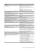
Checkout programs end with either of the following results:
v
The Testing Complete menu is displayed with a message stating
No trouble was found
.
v
The A Problem Was Detected On (Time Stamp) menu is displayed, with either a service request number
(SRN) or an error code. Make a note of any codes displayed on the console or operator panel.
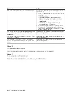
Step 4. Perform additional system verification
To perform additional system verification, do the following:
1. Press
Enter
to return to the Diagnostic Selection menu.
244
NAS Gateway 500 Service Guide
Summary of Contents for TotalStorage NAS Gateway 500
Page 1: ...IBM TotalStorage NAS Gateway 500 Service Guide GY27 0418 00 ...
Page 2: ......
Page 3: ...IBM TotalStorage NAS Gateway 500 Service Guide GY27 0418 00 ...
Page 16: ...xiv NAS Gateway 500 Service Guide ...
Page 20: ...xviii NAS Gateway 500 Service Guide ...
Page 36: ...System logic flow Note Not all components are supported 16 NAS Gateway 500 Service Guide ...
Page 52: ...32 NAS Gateway 500 Service Guide ...
Page 58: ...38 NAS Gateway 500 Service Guide ...
Page 112: ...92 NAS Gateway 500 Service Guide ...
Page 266: ...246 NAS Gateway 500 Service Guide ...
Page 326: ...306 NAS Gateway 500 Service Guide ...
Page 353: ...Chapter 11 Removal and replacement procedures 333 ...
Page 392: ...372 NAS Gateway 500 Service Guide ...
Page 402: ...382 NAS Gateway 500 Service Guide ...
Page 412: ...392 NAS Gateway 500 Service Guide ...
Page 440: ...420 NAS Gateway 500 Service Guide ...
Page 446: ...426 NAS Gateway 500 Service Guide ...
Page 448: ...428 NAS Gateway 500 Service Guide ...
Page 466: ...446 NAS Gateway 500 Service Guide ...
Page 469: ......
Page 470: ... Printed in U S A GY27 0418 00 ...
Page 471: ...Spine information IBM TotalStorage NAS Gateway 500 NAS Gateway 500 Service Guide GY27 0418 00 ...

