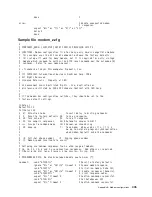
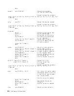
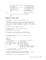
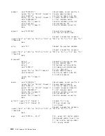
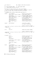
background image

5. Wait for the main display panel.

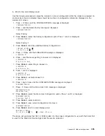
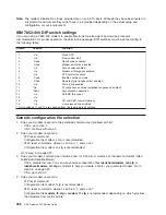
Use the following procedure to place the modem in a known configuration. After the modem is powered on
and local tests have completed, there should be two lines of configuration information displayed on the
modem LCD screen.

1. Press

12 times until the CONFIGURATIONS message is displayed.

CONFIGURATIONS D12

2. Press

until the Select Factory message is displayed.

CONFIGURATIONS D12

Select Factory

3. Press

Enter

to select the Factory configuration option. Press

until 0 is displayed.

CONFIGURATIONS D12

Select Factory 0

4. Press

Enter

to load the predefined factory configuration 0.

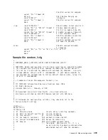
IBM 7857 AT CMD aa

"

td_ rd_ dsr_ ec

"

ll_

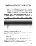
5. Press

7 times until the S-REGISTER message is displayed.

S-REGISTER D7

6. Press

until the message Ring to answer on is displayed.

S-REGISTER D7
Ring to answ. On=2_

7. Press

Enter

to select Ring to answer on.

S-REGISTER D7
Ring to answ. On=_

8. Press

until 0 is displayed.

S-REGISTER D7
Ring to answ. On=0

9. Press

Enter

to set Auto Answer to 0.

S-REGISTER D7

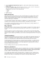
10. Press

key 5 times until the CONFIGURATIONS message is displayed.

CONFIGURATIONS D12

11. Press

3 times until the Store User Conf. message is displayed.

CONFIGURATIONS D12
Store User Conf._

12. Press

Enter

to select the Store User Configuration option. Press

until 0 is displayed.

CONFIGURATIONS D12
Store User Conf. 0

13. Press

Enter

to select location 0.

14. Press

Enter

to save current configuration into User 0.

CONFIGURATIONS D12

15. Press

Enter

to return to main display panel.

IBM 7857 AT CMD aa_
td_ rd_ dsr_ ec

"

ll_

"

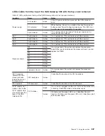
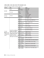
= Shows LCD as on.

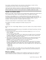
The above set up places the 7857 or 7858 modem into the proper configuration for use with the Dialer that
is used for the Electronic Service Agent and the service processor.

Appendix B. Modem configurations

395

Summary of Contents for TotalStorage NAS Gateway 500

Page 1: ...IBM TotalStorage NAS Gateway 500 Service Guide GY27 0418 00 ...

Page 2: ......

Page 3: ...IBM TotalStorage NAS Gateway 500 Service Guide GY27 0418 00 ...

Page 4: ... Development Department CGF P O Box 12195 Research Triangle Park MC U S A 27709 9990 You can also submit comments by selecting Feedback at www ibm com storage support When you send information to IBM you grant IBM a nonexclusive right to use or distribute the information in any way it believes appropriate without incurring any obligation to you International Business Machines Corporation 2004 All ...

Page 5: ... slots and integrated adapter ports 3 Operator panel 4 Hardware security features 4 Front view of the NAS Gateway 500 with bezel off 5 Back view of the NAS Gateway 500 5 Powering the system on and off 6 Console strategy 6 Power on self test 6 POST indicators 7 POST keys 7 System unit locations 8 Power supply locations 8 Fan locations 9 CEC backplane locations 10 PCI riser card locations 11 DIMM lo...

Page 6: ...rror Codes Table Directed You Here and the Error Code is 1011 1B0x 66 MAP 1540 Problem Isolation Procedures 69 FRU identify LEDs 69 MAP 1541 JTAG Problem Isolation 71 MAP 1542 I O Problem Isolation 72 MAP 1548 Processor Subsystem Problem Isolation 77 MAP 1549 Attention Problem Isolation 90 Chapter 4 Checkpoints 93 IPL flow 93 Service processor checkpoints 94 Firmware checkpoints 101 Boot problems ...

Page 7: ...m additional system verification 244 Step 5 Stop the diagnostics 245 Chapter 8 Hardware problem determination 247 Problem determination using the standalone or online diagnostics 247 Problem determination when unable to load diagnostics 252 Chapter 9 Using the service processor 255 Service processor menus 255 Accessing the service processor menus locally 255 Accessing the service processor menus r...

Page 8: ...t language 294 Change password options 295 View error log 295 Setup remote IPL initial program load 296 Change SCSI settings 299 Select console 299 Select boot options 300 Select boot devices 302 Display current settings 305 Restore default settings 305 Multiboot startup 305 Exiting System Management Services 305 Chapter 11 Removal and replacement procedures 307 Safety considerations 307 Procedure...

Page 9: ... a disk drive 339 Disk drive removal 340 Disk drive replacement 341 Configuring mirroring 342 Processor book 343 Processor book removal 343 Processor book replacement 344 Processor book insertion 344 DIMMs 346 DIMM removal 346 DIMM insertion 347 Battery 348 Power supplies 351 Power supply removal 351 Power supply replacement 352 PCI riser card 354 PCI riser card removal 354 PCI riser card replacem...

Page 10: ...852 400 Modem 394 Configuring the 7857 017 or 7858 336 Modem 394 Generic configuration file selection 396 Transfer of a modem session 399 Modem configuration sample files 401 Appendix C General attributes required when using a TTY terminal 417 Additional communication attributes 418 Additional keyboard attributes 418 Additional printer attributes 419 Appendix D PD data collection worksheets 421 PD...

Page 11: ...or functions and menus Chapter 9 Using the service processor on page 255 There should also be a service console connected to serial port 1 to allow a connection to the NAS Gateway 500 service processor menus and POST messages It can also be used to access the NAS Gateway 500 SMIT panels To start solving serviceable events on the NAS Gateway 500 service analysis should begin with Chapter 3 Maintena...

Page 12: ...ion Guide GA27 4336 U U IBM TotalStorage NAS Gateway 500 Quick Start Instructions GX27 4026 00 U IBM TotalStorage NAS Gateway 500 Administrator s Guide SC30 4072 U U U IBM TotalStorage NAS Gateway 500 Command Reference SC30 4074 U U U U IBM TotalStorage NAS Gateway 500 CIFS File Serving Guide SC30 4075 U U U IBM TotalStorage NAS Gateway 500 Service Guide GY27 0418 U U U IBM TotalStorage NAS Gatewa...

Page 13: ...ers storage support The following publications contain additional information about the NAS Gateway 500 v IBM TotalStorage NAS Gateway 500 Planning Guide GA27 4335 This manual describes the requirements to consider when planning the installation of the IBM TotalStorage NAS Gateway 500 v IBM TotalStorage NAS Gateway 500 Advanced Configuration and Problem Determination Guide SC30 4073 This manual pr...

Page 14: ...AIX 5L Version 5 2 Performance Tools Guide and Reference v AIX 5L Version 5 2 Security Guide v AIX 5L Version 5 2 System Management Concepts Operating System and Devices v AIX 5L Version 5 2 System Management Guide Communications and Networks v AIX 5L Version 5 2 System Management Guide Operating System and Devices v AIX 5L Version 5 2 System User s Guide Communications and Networks v AIX 5L Versi...

Page 15: ...ects such as buttons labels and icons that the user selects Italics Identifies parameters whose actual names or values are to be supplied by the user Monospace Identifies examples of specific data values examples of text similar to what you might see displayed examples of portions of program code similar to what you might write as a programmer messages from the system or information that you actua...

Page 16: ...xiv NAS Gateway 500 Service Guide ...

Page 17: ...l loading when installing this unit in a rack If the rack has a stabilizer it must be firmly attached before installing or removing this unit v Consider and inspect the connection of the equipment to the supply circuit to ensure that overloading of circuits does not compromise the supply wiring or overcurrent protection To provide the correct power connection to the rack refer to the rating labels...

Page 18: ... products Outside the U S they are certified to be in compliance with the IEC 825 first edition 1984 as a class 1 laser product Consult the label on each part for laser certification numbers and approval information CAUTION All IBM laser modules are designed so that there is never any human access to laser radiation above a class 1 level during normal operation user maintenance or prescribed servi...

Page 19: ...omponent failures must verify the accuracy of operations performed and data saved or transmitted by the system at or near the time of the outage or failure In addition users must establish procedures to ensure that there is independent data verification before relying on such data in sensitive or critical operations Users should periodically check the IBM support Web sites for updated information ...

Page 20: ...xviii NAS Gateway 500 Service Guide ...

Page 21: ...stem cables v Specifications v External AC power cables v Service inspection guide Overview The NAS Gateway 500 is a four Electronic Industries Association EIA unit drawer designed to be housed in a 19 inch rack It can be configured as a two way or four way symmetric multiprocessing SMP system it can have up to two hot plug disk drives and six hot plug PCI X adapters It has redundant hot plug powe...

Page 22: ...ystem 1 PCI X adapter slot locations Processor books v Each NAS Gateway 500 has one or two processor books The processor books are mechanical assemblies that contain a two way processor card Each of the two processors on this card has a dedicated 8 MB L2 cache and these processors share a common 64 MB L3 cache v L3 cache capacity per processor configuration Two way configuration One L3 chip with a...

Page 23: ...rnal Ultra3 SCSI one external Ultra3 SCSI with VHDCI 4 mini 68 pin port v Three serial ports Serial port 1 S1 has two physical connectors one RJ 48 connector located in front on the operator panel and a 9 pin D shell connector located on the back of the chassis The use of the front connector disables the back S1 connector Serial port 2 S2 has a 9 pin D shell connector on the back of the system cha...

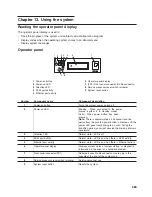
Page 24: ...erator panel The following figure shows the operator panel 1 Power on button 2 Power on LED blinks when in standby 3 Attention LED 4 SCSI port activity LED 5 Ethernet port activity LED 6 32 character operator panel diagnostics display 7 FS1 Front serial connector RJ 48 connector 8 Service processor reset switch pinhole 9 System reset button amber Hardware security features On the NAS Gateway 500 y...

Page 25: ... SPCN1 not supported 5 System power control network connector SPCN2 not supported 6 Parallel connector not supported 7 Hardware Management Console connector HMC2 not supported 8 Hardware Management Console connector HMC1 not supported 9 Ethernet connector 1 10 Ethernet connector 2 11 RIO 0 and RIO 1 connectors not supported 12 Serial connector 2 13 Serial connector 3 14 Serial connector 1 15 Mouse...

Page 26: ...ration affects the console The console selection sequence allows you to select from the appropriate input device any one of the available console devices If no console is selected within approximately 60 seconds serial port 1 S1 is selected as the console and the selection sequence times out Attention If an ASCII terminal is attached to serial port 1 S1 and there is any interaction with this termi...

Page 27: ... and diagnosing problems The keys are described below 1 key The numeric 1 key when pressed during POST starts the System Management Services SMS interface 5 key The numeric 5 key when pressed during POST initiates a system boot in service mode using the default service mode boot list This mode attempts to boot from the first device of each type found in the list It does not search for other bootab...

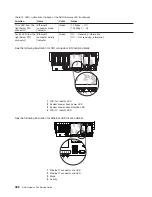
Page 28: ...System unit locations Power supply locations 1 Power supply 1 3 AC good LED green 2 Power supply 2 4 DC good LED green 5 Fault LED amber 8 NAS Gateway 500 Service Guide ...

Page 29: ...o groups of three LEDs located on the front and top The amber LED on the power supply indicates a problem with the power supply If a power supply is diagnosed with a cooling problem the entire power supply must be replaced 1 2 3 4 5 5 1 Processor card cooling fan 1 4 PCI X adapter cooling fan 3 2 Processor card cooling fan 2 5 Stacked power supply cooling fans 3 PCI X adapter cooling fan 4 Chapter...

Page 30: ...attery connector 7 Parallel port connector not supported 23 For manufacturing use only 8 HMC1 connector not supported 24 PCI X cooling fan 3 and 4 connector 9 Ethernet 1 connector 25 IDE CD ROM signal connector 10 Ethernet 2 connector 26 Diskette drive signal connector 11 Connector RIO G1 connector not supported 27 Diskette drive power connector 12 Processor cooling fan 1 connector 28 Media power ...

Page 31: ...wing illustration shows the PCI X adapter slot locations when viewing from the back of the system 2 1 3 4 5 6 The following illustration shows the connector and slot locations on the PCI riser card 1 10 11 15 12 13 14 2 3 4 5 6 9 8 7 1 PCI X slot 1 9 Riser card 2 PCI X slot 2 10 Push labels 3 PCI X slot 3 11 Internal disk drive SCSI connector for internal disk drive use only 4 PCI X slot 4 12 Sing...

Page 32: ... at least four DIMMs installed one quad v The quad slot combinations are M1 M3 M6 and M8 or M2 M4 M5 and M7 Note M1 M3 M6 and M8 or M2 M4 M5 and M7 combinations are the only possible slot combinations recognized by the system Table 4 shows valid memory configurations when only one FC 5127 processor book is installed You can have only one of the memory configurations identified by each row of Table...

Page 33: ...location codes for processor card 1 If your system is configured for processor card 2 substitute C2 in place of C1 Memory rules For optimal performance memory should be balanced between the two processor boards If you do not balance the memory correctly the NAS Gateway 500 will function with reduced performance Memory placement rules v All memory FCs contain four DIMMs of equal size one quad v Mem...

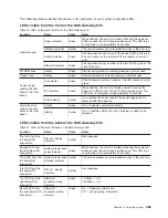
Page 34: ...period from the time the power button is pressed to when the power LED goes from blinking to solid During the transition period you might observe the blinking intervals speed up 3 Attention LED Normal state LED is off 4 SCSI port activity Normal State LED is on when there is SCSI activity 5 Ethernet port activity Normal state LED is on when there is Ethernet activity 6 Operator panel display Displ...

Page 35: ... 1 Operator panel 2 D01 IDE CD ROM IDE Non SCSI 3 D02 Diskette drive SCSI ID 0 4 D10 base OS Disk drive SCSI ID 8 5 D11 OS mirroring Disk drive optional SCSI ID 9 Note The SCSI bus IDs are the recommended values and indicate how the IDs are set when the system is shipped from the factory Field installations might not comply with these recommendations Chapter 1 Reference information 15 ...

Page 36: ...System logic flow Note Not all components are supported 16 NAS Gateway 500 Service Guide ...

Page 37: ...le P2 S1 describes the location of the serial port 1 controller and its connector S1 which is located on planar P2 its base location code but the indicates that further devices can be connected to it at the external S1 serial connector The location code P2 Z1 indicates an integrated SCSI controller that drives connector Z1 although location codes of P2 Z1 point to the actual SCSI bus and devices v...

Page 38: ...ds EF is the connector ID It is used to identify the adapter s connector to which a resource is attached GH is used to identify a port device or FRU For example v For a diskette drive H identifies either diskette drive 1 or 2 G is always 0 v For all other devices GH is equal to 00 For an integrated adapter EF GH is the same as the definition for a pluggable adapter For example the location code fo...

Page 39: ...includes a blank space followed by a lowercase x followed by a number this is an error code with multiple FRU callouts This error can typically happen with DIMMs or processors and might involve mixed types of parts In this case check the system s configuration for FRU part numbers to determine the appropriate set of FRUs To determine the FRU part numbers of the electronic assemblies in the entire ...

Page 40: ...Identify and Attention Indicators task through diagnostics The procedure to operate the Identify and Attention Indicators task in diagnostics is outlined in the RS 6000 Eserver pSeries Diagnostic Information for Multiple Bus Systems 20 NAS Gateway 500 Service Guide ...

Page 41: ...1 P1 S3 U0 1 P1 S1 U0 1 P1 Q1 U0 1 P1 Q3 U0 1 P1 Q2 U0 1 P1 E2 U0 1 P1 E1 U0 1 P1 O1 U0 1 P1 K1 U0 1 P1 Q4 U0 1 P1 Q5 U0 1 P1 S4 U0 1 P1 S5 U0 1 P1 R1 U0 1 P2 Z2 U0 1 V1 U0 1 F2 AIX Location Codes AIX Location Codes Physical Location Codes Physical Location Codes U0 1 V2 01 D1 U0 1 F1 U0 1 F3 U0 1 F4 U0 1 P1 V3 U0 1 P2 U0 1 P1 C1 U0 1 P1 Q6 U0 1 P1 D1 U0 1 P3 U0 1 P2 Ix Zn A1 U0 1 L1 U0 1 P1 C2 Ch...

Page 42: ... M1 U0 1 P1 C2 M1 U0 1 P1 C1 M2 U0 1 P1 C2 M2 U0 1 P1 C1 M6 U0 1 P1 C2 M6 U0 1 P1 C1 M3 U0 1 P1 C2 M3 U0 1 P1 C1 M7 U0 1 P1 C2 M7 U0 1 P1 C1 M4 U0 1 P1 C2 M4 U0 1 P1 C1 M8 U0 1 P1 C2 M8 U0 1 P1 C1 M5 U0 1 P1 C2 M5 Processor Card 1 Processor Card 2 Physical Location Codes Physical Location Codes 22 NAS Gateway 500 Service Guide ...

Page 43: ...AIX Location Codes Physical Location Codes Physical Location Codes 11 08 1Z 08 1D 08 1n 08 1S 09 1S 08 00 15 0 1V 08 1c 08 1S 08 1H 08 Disk drive backplane location codes Use the following illustration to aid you in the mapping of a location code to its slot on the disk drive backplane U0 1 P2 Z1 A8 U0 1 P2 Z1 A9 U0 1 P2 Z1 AA U0 1 P2 Z1 AB AIX Location Codes Physical Location Codes 1S 08 00 8 0 1...

Page 44: ... DIMM 3 U0 1 P1 C1 M3 DIMM 4 U0 1 P1 C1 M4 DIMM 5 U0 1 P1 C1 M5 DIMM 6 U0 1 P1 C1 M6 DIMM 7 U0 1 P1 C1 M7 DIMM 8 U0 1 P1 C1 M8 DIMMs on processor card 2 DIMM 1 U0 1 P1 C2 M1 DIMM 2 U0 1 P1 C2 M2 DIMM 3 U0 1 P1 C2 M3 DIMM 4 U0 1 P1 C2 M4 DIMM 5 U0 1 P1 C2 M5 DIMM 6 U0 1 P1 C2 M6 DIMM 7 U0 1 P1 C2 M7 DIMM 8 U0 1 P1 C2 M8 Integrated devices Debug connector manufacturing use only Labeled debug connect...

Page 45: ...Base CD ROM IDE controller U0 1 P1 Q6 1G 19 Pluggable adapters PCI host bridge 0 U0 1 P2 PCI host bridge 1 U0 1 P2 PCI X slot 1 U0 1 P2 I1 PCI X slot 1 card U0 1 P2 I1 1V 08 PCI X slot 2 U0 1 P2 I2 PCI X slot 2 card U0 1 P2 I2 1H 08 PCI host bridge 2 U0 1 P2 PCI X slot 3 U0 1 P2 I3 PCI X slot 3 card U0 1 P2 I3 1n 08 PCI X slot 4 U0 1 P2 I4 PCI X slot 4 card U0 1 P2 I4 1Z 08 PCI X slot 5 U0 1 P2 I5...

Page 46: ...1 U0 1 V1 Power supply 2 U0 1 V2 Battery Battery U0 1 P1 V3 Platform firmware Platform firmware U0 1 P1 Y1 System VPD module System VPD module U0 1 L1 N1 Notes 1 The physical location code for the PCI X slots when empty uses the P1 Ix notation where the identifies an integrated device in this case the empty slot A PCI X device plugged into the slot uses the P1 Ix notation where the identifies a pl...

Page 47: ...D ROM 3 SCSI media device not supported 4 CEC backplane to operator panel signal power cable 5 Two drop power cable from CEC backplane to IDE CD ROM and other SCSI media devices second connector unused 6 CEC backplane to disk drive backplane power cable 7 Disk drive backplane 8 Diskette drive to CEC backplane power cable 9 PCI X cooling fans 3 and 4 power cable 10 Diskette drive 11 CEC backplane C...

Page 48: ...ded SCSI connector on the PCI riser card not supported 8 CEC backplane connector to diskette drive signal cable 9 CEC backplane to IDE CD ROM signal cable 10 Diskette drive 11 IDE CD ROM 12 Disk drive backplane 13 PCI riser card to disk drive backplane signal cable 14 PCI riser card to disk drive backplane signal cable 15 PCI riser card 16 CEC backplane 17 PCI riser card to external SCSI signal ca...

Page 49: ...80 Wet bulb 27 C 80 F Noise emissions1 5 6 Operating LWAd 6 1 bels LpA m 44 dBA Installation and air flow Maintenance of service clearance will allow proper air flow 1 Noise emission notes a LWAd is the declared sound power emission level for a production series of machines b LpAm is the mean value of the sound pressure emission levels at the operator position if any for a production series of mac...

Page 50: ...in the United States use a UL listed cable set consisting of a minimum 18 AWG Type SVT or SJT three conductor cable a maximum of 15 feet in length and a tandem blade grounding type attachment plug rated at 15 A 250 V v Appliance couplers complying with International Electrotechnical Commission IEC Standard 320 Sheet C13 Power cables used in other countries consist of the following v Electrical cab...

Page 51: ...per fit to the system They should be in place and secure 4 Remove the covers 5 Check for alterations or attachments If there are any check for obvious safety hazards such as broken wires sharp edges or broken insulation 6 Check the internal cables for damage 7 Check for dirt water and any other contamination within the system 8 Check the voltage label on the back of the system to ensure that it ma...

Page 52: ...32 NAS Gateway 500 Service Guide ...

Page 53: ...20 Problem Determination v MAP 1240 Memory Problem Resolution v MAP 1520 Power v MAP 1521 The Base System Drawer Will Not Power On and No Error Codes Are Available v MAP 1523 The SPCN Error Codes Table Directed You Here and the Error Code is 1011 1B0x v MAP 1540 Problem Isolation Procedures v MAP 1541 JTAG Problem Isolation v MAP 1542 I O Problem Isolation v MAP 1548 Processor Subsystem Problem Is...

Page 54: ...nel Note Certain checkpoints might remain in the operator panel for long periods of time A spinning cursor is visible in the upper right corner of the operator panel during these periods to indicate that system activity is continuing Exxx Exxx checkpoints indicate that a system processor is in control and is initializing the system resources Control is being passed to the operating system when E10...

Page 55: ...rt identify LED not supported v Various FRU identify LEDs Power subsystem FRUs CEC subsystem FRUs I O subsystem FRUs PCI X adapter identify LED DASD identify LED See Component LEDs on page 384 Any identify LED in the system can be flashed when the system is in the failed state with power on by using the service processor LED Control Menu contained in the System information menu on page 268 Any ide...

Page 56: ...in the service processor error log When the LED is on it indicates that user intervention or service is needed The error entry is transmitted and recorded in the following logs v The service processor error log v The operating system error log If the system attention LED is turned on you can access the system logs to determine the reason The method used to access your system logs depends on how yo...

Page 57: ...elect Task Selection 2 On the Task Selection Menu select Identify and Attention Indicators 3 When the list of LEDs is displayed use the cursor to highlight Set System Attention Indicator to Normal 4 Press Enter and then press F7 to commit This action turns off the LED If the system is powered off access the service processor menus From the service processor main menu do the following 1 Select Syst...

Page 58: ...38 NAS Gateway 500 Service Guide ...

Page 59: ...otified so that the adapter definitions on the back end storage and the fibre channel zones on the SAN switches can be updated with the World Wide Name WWN of the new adapter 4 If more than eight digits are displayed in the operator panel use only the first eight digits to find the error in the tables The digits that display beyond the first eight digits are location codes that can assist you in d...

Page 60: ...git number displayed that does not begin with 0 or 2 41 System stops with a 3 digit number displayed see below for 888 sequence 41 Power and cooling problems 42 888 sequence in operator panel 42 Other symptoms or problems 42 Attention If you replace FRUs or perform an action and the problem is still not corrected go to MAP 1540 Problem Isolation Procedures on page 69 unless you were directed to MA...

Page 61: ...ocessor menu is not displayed replace the CEC backplane See Central electronics complex CEC backplane on page 366 If an ASCII terminal is not available replace the following one at a time 1 Operator panel assembly location U0 1 L1 Refer to Operator panel on page 362 2 CEC backplane location U0 1 P1 See Central electronics complex CEC backplane on page 366 You have a blank display on the operator p...

Page 62: ...r panel is on and there is no error code displayed 1 Check the service processor error log 2 Go to MAP 1520 Power on page 58 888 sequence in operator panel An 888 sequence is displayed in the operator panel Go to the Fast Path MAP in the RS 6000 Eserver pSeries Diagnostic Information for Multiple Bus Systems Other symptoms or problems The operator panels OK and the fans are off The service process...

Page 63: ...the VPD module from the old operator panel to the new operator panel See Operator panel on page 362 2 CEC backplane location U0 1 P1 See Central electronics complex CEC backplane on page 366 If the problem is fixed go to MAP 0410 Repair Checkout on page 45 If the problem is still not corrected go to MAP 1548 Processor Subsystem Problem Isolation on page 77 Symptom The SMS configuration list or boo...

Page 64: ...3 If the error was logged during the current boot attempt record it 4 Look up the error in Chapter 5 Error code to FRU index on page 125 and do the listed action 5 If no recent error is logged in the error log try to boot from an alternate boot device connected to the same controller as the original boot device If the boot succeeds replace the original boot device for removable media devices try t...

Page 65: ...is that you want to put back into the system NO Go to Step 0410 4 YES Go to Step 0410 3 Step 0410 3 1 After performing a system shutdown turn off the system power and unplug all power cords cables from electrical outlets 2 Install all of the cards adapters cables devices and any other FRUs that were removed during problem analysis 3 Go to step Step 0410 4 Step 0410 4 1 Set slow boot using the serv...

Page 66: ...display NO Go to Step 0410 8 YES Go to Step 0410 9 Step 0410 8 Did the Testing Complete no trouble was found menu 801010 display NO There is still a problem Go to MAP 1020 Problem Determination on page 49 YES Use the Log Repair Action option if not previously logged in the Task Selection menu to update the system error log If the repair action was reseating a cable or adapter select the resource a...

Page 67: ...the following 1 From the Resource Repair Action menu select the parent or child of the resource that has been replaced If the repair action was reseating a cable or adapter select the resource associated with that repair action If the resource associated with your action is not displayed on the Resource List select sysplanar0 2 Press Commit after you make your selections 3 If the No Trouble Found ...

Page 68: ...Step 0410 13 This completes the repair return the system to the user 48 NAS Gateway 500 Service Guide ...

Page 69: ...ould cause the system to power on Following are the service processor settings The service processor menus are described in the NAS Gateway 500 Administrator s Guide Surveillance From the service processor Setup Menu go to the Surveillance Setup Menu and disable surveillance Unattended start From the service processor System Power Control Menu disable unattended start mode Reboot policy From the S...

Page 70: ...a valid password go to the beginning of this table and wait for one of the other conditions to occur The diagnostic operating instructions are displayed Go to MAP 0020 Problem Determination Procedure in the RS 6000 Eserver pSeries Diagnostic Information for Multiple Bus Systems Symptom The system login prompt is displayed Action If you are loading the diagnostics from a CD ROM you might not have p...

Page 71: ...ror was logged during the current boot attempt record it 4 Look up the error in Chapter 5 Error code to FRU index on page 125 and do the listed action 5 If no recent error is logged in the error log try to boot from an alternate boot device connected to the same controller as the original boot device If the boot succeeds replace the original boot device for removable media devices try the media fi...

Page 72: ...er to monitor service operations and to attempt recoveries You might want to disable these actions while you diagnose and service the system If you disable them make note of their current settings so that you can restore them before you leave The following settings might be of interest to you Surveillance From the Service Processor Setup Menu go to the Surveillance Setup menu and disable surveilla...

Page 73: ...oblem Enable memory repeat gard if necessary Go to MAP 0410 Repair Checkout on page 45 Yes If there is only 1 processor card installed tag it as suspect bad and go to Step 1240 6 on page 54 If there are 2 processor cards installed go to Step 1240 2 Step 1240 2 1 Turn off the power Remove the power cords 2 Remove processor card 2 3 Reattach the power cords Wait for OK to display in the operator pan...

Page 74: ...n off the power Remove the power cords 2 Exchange the following FRUs one at a time in the order listed v CEC backplane v Processor cards 3 Reattach the power cords Wait for OK to display in the operator panel 4 Turn on the power Attempt to boot to the SMS menus The system might stop with an 8 digit error code before it reaches the SMS menus 5 Power off the system using the white power button After...

Page 75: ...Attempt to boot to the SMS menus The system might stop with an 8 digit error code before it reaches the SMS menus 5 Power off the system using the white power button After OK is displayed in the operator panel look at the memory configuration deconfiguration menu Are any DIMMs deconfigured or does the error code recorded in Step 1240 1 on page 53 still appear NO Go to Step 1240 8 YES Go to Step 12...

Page 76: ...tention If only one quad of DIMMs is on the processor card you must have at least one replacement DIMM of the same size and speed as the DIMMs that are on the card If there were two quad of DIMMs on the processor card but they are not the same size your must have at least one replacement DIMM of the same size and speed as the DIMMs in the quad that is failing If there were two quad of DIMMs on the...

Page 77: ...MM of the quad on the processor card YES Go to Step 1240 13 Step 1240 13 Did the processor originally have only one quad of DIMMs at the start of this map NO Call service support YES Replace the processor card This ends the procedure Enable memory repeat gard if necessary Go to MAP 0410 Repair Checkout on page 45 Chapter 3 Maintenance Analysis Procedures MAPs 57 ...

Page 78: ...the following safety notices during service procedures DANGER An electrical outlet that is not correctly wired could place hazardous voltage on metal parts of the system or the devices that attach to the system It is the responsibility of the customer to ensure that the outlet is correctly wired and grounded to prevent an electrical shock D09 Before installing or removing signal cables ensure that...

Page 79: ...rvice processor LED Control Menu contained in the System information menu on page 268 Any identify LED in the system can also be flashed by using the Identify and Attention Indicators task through diagnostics The procedure to operate the Identify and Attention Indicators task in diagnostics is outlined in the RS 6000 Eserver pSeries Diagnostic Information for Multiple Bus Systems Symptom Action Th...

Page 80: ...ed The power LED located on the operator panel does not come on None of the cooling fans start to turn Go to Step 1521 7 on page 62 v The AC power supply power LEDs are on The power LED located on the operator panel is blinking and OK is displayed on the operator panel When the power button on the operator panel is pressed the power LED on the operator panel comes on and all the fans start to turn...

Page 81: ...rrect voltage Did you find a problem NO Go to Step 1521 6 YES Correct the problem Go to MAP 0410 Repair Checkout on page 45 Step 1521 6 1 One of the following might be defective v Power supplies v CEC backplane v DIMMs v Processor books 2 To test each FRU exchange the FRUs that have not already been exchanged in the following order v Power supply 1 v Power supply 2 v CEC backplane v DIMMs v Proces...

Page 82: ...sor book 2 if installed 6 Unplug the signal and power cables from the DASD backplane 7 Unplug the disk drives from the DASD backplane 8 Unplug the signal and power cables from any devices in the media bays 9 Remove all the fans 10 Plug the power cables into the system unit 11 Turn on the power Does the power LED on the operator panel come on and stay on NO Go to Step 1521 9 YES Go to Step 1521 10 ...

Page 83: ...f the power 2 Unplug the power cables from the system unit 3 Install or connect one of the parts in the list 4 Plug the power cables into the system unit 5 Turn on the power Does the power LED on the operator panel come on and stay on NO Replace the last part installed v If DIMMs on the first processor card were the last parts installed exchange the DIMMs one at a time to isolate the failing modul...

Page 84: ...521 14 Because the NAS Gateway 500 has redundant power supplies it is not necessary to power off the system when replacing a power supply The power supplies are symmetrical so replacement starts with the unit closest to the system wall of the system power supply 1 For instructions on replacing a power supply refer to Power supplies on page 351 Notes 1 Always service first the power supply whose gr...

Page 85: ...stem and perform error log analysis Do you get an SRN indicating that a voltage sensor is out of range NO The last FRU exchanged is defective Go to MAP 0410 Repair Checkout on page 45 YES Reinstall the original FRU Repeat the FRU replacement steps until a defective FRU is identified or all the FRUs have been exchanged If the symptom did not change and all FRUs have been exchanged go to Step 1521 1...

Page 86: ...em 5 Turn on the power Is the error code 1011 1B0x displayed NO Go to Step 1523 7 on page 67 YES Go to Step 1523 2 Step 1523 2 1 Turn off the power 2 Disconnect the AC power cables from the system 3 Remove system power supply 2 4 Reconnect the AC power cable to the system power supply 1 5 Turn on the power Is the error code 1011 1B0x displayed NO Go to Step 1523 3 YES Go to Step 1523 4 on page 67 ...

Page 87: ...uring this step 5 Turn on the power Is the error code 1011 1B0x displayed NO Replace system fan 3 location U0 1 F3 This ends the procedure Go to MAP 0410 Repair Checkout on page 45 YES Go to Step 1523 6 Step 1523 6 1 Turn off the power 2 Reinstall system fan 3 that was removed in Step 1523 5 3 Remove system fan 4 Disregard a system fan error code if it occurs during this step 4 Turn on the power I...

Page 88: ... last card that you installed This ends the procedure Go to MAP 0410 Repair Checkout on page 45 Step 1523 8 Have all the cards that were removed in Step 1523 7 on page 67 been reinstalled NO Go to Step 1523 7 on page 67 and reinstall the next assembly in the list YES Replace the system backplane location U0 1 P1 This ends the procedure Go to MAP 0410 Repair Checkout on page 45 68 NAS Gateway 500 S...

Page 89: ...llowing v Various FRU identify LEDs Power subsystem FRUs CEC subsystem FRUs I O subsystem FRUs PCI X adapter identify LED DASD identify LED Any identify LED in the system can be flashed when the system is in the failed state with power on by using the service processor LED Control Menu contained in the System information menu on page 268 Any identify LED in the system can also be flashed by using ...

Page 90: ... Processor Subsystem Problem Isolation on page 77 E101 E102 E10A E10B E111 E120 E121 E122 E130 E131 E132 E133 E134 E135 E138 E139 E13A E149 E14C E191 E19A E19B E19D E1A0 E1A1 E1A2 E1A3 E1A4 E1A5 E1A6 E1A7 E1A8 E1A9 E1AA E1AB E1AC E1AD E1AE E1AF E1B1 E1C4 E1C5 E1C6 E1D0 E1D3 E1D4 E1DB E1F0 E1F1 E1F4 E1F5 E1F6 E1F8 E1F9 E1FA E1FB E1FD E1FE E5E0 E5E2 E5E3 E5E4 E5E5 E5E6 E5E7 E5E8 E5E9 E5EE E5EF B1xx ...

Page 91: ...sor card 1 at location U0 1 P1 C1 Mn n equals 1 to 8 if not recorded in Step 1541 1 v Processor card at location U0 1 P1 C2 if not recorded in Step 1541 1 v All DIMMs on processor card 2 at location U0 1 P1 C2 Mn n equals 1 to 8 if not recorded in Step 1541 1 v PCI riser card at U0 1 P2 Step 1541 4 Turn on the power Step 1541 5 Did the system stop with the same error code as recorded in Step 1541 ...

Page 92: ...s error log It is a good idea to examine that error log before proceeding See Accessing system error logs on page 36 5 The service processor might have been set by the user to monitor system operations and to attempt recoveries You can disable these actions while you diagnose and service the system If you disable them make notes of their current settings so that you can restore them easily The fol...

Page 93: ...ssor subsystem problem Call service support This ends the procedure YES Restore fast boot mode select Enable Fast Boot on the System Power Control menu from the service processor main menu Go to Checkpoint and error code index on page 127 and follow the actions for the new error code Step 1542 4 The system stopped with the Please define system console prompt appearing on the system console Standal...

Page 94: ...D ROM 2 If the Please Define the System Console prompt is displayed follow directions to select the system console 3 Use the Display Configuration and Resource List to list all attached devices and adapters refer to the RS 6000 Eserver pSeries Diagnostic Information for Multiple Bus Systems if necessary 4 Check that all attached devices and adapters are listed If the Please Define the System Conso...

Page 95: ... displayed follow directions to select the system console 8 Use the Display Configuration and Resource List to list all attached devices and adapters refer to the RS 6000 Eserver pSeries Diagnostic Information for Multiple Bus Systems if necessary 9 Check that all attached devices and adapters are listed Is the Please Define the System Console prompt displayed and are all attached devices and adap...

Page 96: ...tep 1542 8 on page 74 YES Go to Step 1542 6 on page 74 Step 1542 13 1 Turn off the power 2 Disconnect the system power cables 3 Replace the following parts one at a time in the sequence listed a Internal SCSI cable b DASD backplane c Media backplane 4 Reconnect the system power cables 5 Turn on the power 6 Boot standalone diagnostics from CD ROM 7 If the Please Define the System Console prompt is ...

Page 97: ...at the error that occurred just before the original error Perform the actions associated with that error If the problem is not resolved go to Step 1548 1 on page 78 v If a slow boot results in the same error code and there are no error codes before the original error code go to Step 1548 1 on page 78 Before proceeding it is a good idea to examine that error log See Accessing system error logs on p...

Page 98: ...ssor with the instructions in note 7 on page 77 Then return here and continue 3 Exit the service processor menus and remove the power cords 4 Disconnect all external cables serial port 1 serial port 2 Ethernet and so on 5 Place the drawer of the NAS Gateway 500 into the service position and remove the service access cover 6 Record the slot numbers of the PCI adapters Label and record the locations...

Page 99: ...14 If your system is equipped with a diskette drive disconnect the diskette drive cable from the diskette drive connector on the CEC backplane 15 Disconnect the signal and power connectors from the disk drive backplane 16 Disconnect the disk drives from the disk drive backplane connectors 17 Reinstall the media tray 18 Plug in the power cords and wait for the operator panel to display OK 19 Turn o...

Page 100: ...in the system unit is defective Note If a DIMM is exchanged ensure that the new DIMM is the same size and speed as the original DIMM 1 Turn off the power remove the power cords and exchange the following FRUs in the order listed a DIMMs Exchange one at a time with new or previously removed DIMMs b Processor card 1 c CEC backplane d PCI riser card e Power supplies 2 Plug in the power cords and wait...

Page 101: ...w symptom YES Go to Step 1548 8 Step 1548 8 1 Turn off the power 2 Reconnect the system console Note If an ASCII terminal has been defined as the system console attach the ASCII terminal cable to the S1 connector on the back of the system unit 3 Turn on the power 4 If the ASCII terminal is connected differently than it was before the Console Selection panel appears and requires that a new console ...

Page 102: ... obvious problems If you do not find a problem go to the Quick Entry MAP on page 40 and follow the instructions for the new symptom YES Go to Step 1548 10 Step 1548 10 The system is working correctly with this configuration One of the SCSI devices that you disconnected might be defective 1 Make sure the diagnostic CD ROM is inserted into the CD ROM drive 2 Turn off the power and remove the power c...

Page 103: ... If you are prompted to do so enter the appropriate password Is the Please Define the System Console prompt displayed NO One of the FRUs remaining in the system unit is defective Exchange the FRUs that have not been exchanged in the following order 1 SCSI cable 2 Disk drive backplane Repeat this step until the defective FRU is identified or all the FRUs have been exchanged If the symptom did not c...

Page 104: ...e operator panel to display OK 6 Turn on the power 7 After the word keyboard is displayed press 5 on the ASCII terminal keyboard 8 If you are prompted to do so enter the appropriate password Is the Please Define the System Console prompt displayed NO One of the FRUs remaining in the system is defective Exchange the FRUs that have not been exchanged in the following order 1 Diskette drive 2 Diskett...

Page 105: ...ower cords 2 Install an adapter and connect any cables and devices that were attached to the FRU 3 Plug in the power cords and wait for the operator panel to display OK 4 Turn on the power 5 If the Console Selection panel is displayed choose the system console 6 After the word keyboard is displayed press 5 on the ASCII terminal keyboard 7 If you are prompted to do so enter the appropriate password...

Page 106: ...nitialize Terminal option on the Function Selection menu to initialize the AIX diagnostic environment before you can continue with the diagnostics This is a separate operation from selecting the console display 5 If the New Resource panel is displayed select an option from the bottom of the panel Note Adapters or devices that require supplemental media are not shown in the new resource list If the...

Page 107: ...n panel after the supplemental media was processed NO Go to Step 1548 22 YES Press F3 to return to the Function Selection panel Go to Step 1548 17 on page 86 substep 4 Step 1548 22 The adapter or device is probably defective If the supplemental media is for an adapter replace the FRUs in the following order 1 Adapter 2 CEC backplane If the supplemental media is for a device replace the FRUs in the...

Page 108: ...OK 3 Turn on the power Does the system stop with the same error code displayed on the operator panel that directed you to this MAP step NO Go to MAP 0410 Repair Checkout on page 45 YES Reinstall the original FRU If the symptom did not change and all the FRUs have been exchanged return to Step 1548 2 on page 78 Step 1548 25 The system is working correctly with this configuration One of the FRUs ada...

Page 109: ...disconnected is defective Exchange the defective device or cable Go to MAP 0410 Repair Checkout on page 45 YES Repeat this step until the defective device or cable is identified or all of the devices and cables have been disconnected If all of the devices and cables have been removed then one of the FRUs remaining in the system unit is defective To test each FRU exchange the FRUs in the following ...

Page 110: ...B8 Go to Step 1549 7 on page 91 406x 0EB9 Go to Step 1549 7 on page 91 406x 0EBA Go to Step 1549 7 on page 91 406x 0EBB Go to Step 1549 7 on page 91 406x 0EBC Go to Step 1549 7 on page 91 Step 1549 4 Replace the following cards if present one at a time v First location code item recorded if any in Step 1549 1 v Second location code item recorded if any in Step 1549 1 v Third location code item rec...

Page 111: ... location code item recorded if any in Step 1549 1 on page 90 v Third location code item recorded if any in Step 1549 1 on page 90 Attention Before replacing the system backplane call support v CEC backplane at U0 1 P1 if not recorded in Step 1549 1 on page 90 Step 1549 8 Turn on the power Step 1549 9 Did the system stop with the same error code as recorded in Step 1549 1 on page 90 No The card th...

Page 112: ...92 NAS Gateway 500 Service Guide ...

Page 113: ... 3 a system processor takes over control During this phase checkpoints in the form Exxx are displayed E105 the last checkpoint in this phase indicates that control is being passed to the operating system boot program v Phase 4 Operating system boot When the operating system starts to boot checkpoints in the form 0xxx and 2xxx are displayed This phase ends when the operating system login prompt is ...

Page 114: ...ed in the checkpoint tables but does not contain a repair action or FRU listing v A four digit code in the range of E500 through E6FF except E5Ex see note 1 above in which all of the FRUs listed have been replaced or service actions have been performed and the problem has not been corrected Checkpoints listed in the following tables are in the format 8xxx 9xxx Axxx Bxxx or Exxx where x is any hexa...

Page 115: ...irmware update See note 3 on page 100 8098 Firmware image being read during recovery mode system firmware update See note 3 on page 100 809C Firmware image being written during recovery mode system firmware update See note 3 on page 100 809F Diskette error during recovery mode system firmware update See note 3 on page 100 8100 Start operational loader See note 1 on page 100 81xx Load code into DRA...

Page 116: ...nu interface thread See note 1 on page 100 906C Create general thread See note 1 on page 100 906D Create SPCN thread See note 1 on page 100 9070 Create thread to control LEDs on I O subsystems See note 1 on page 100 9071 Initialize thread to control LEDs on I O subsystems See note 1 on page 100 9080 Start VPD collection program See note 1 on page 100 9081 Start SC VPD data collection See note 1 on...

Page 117: ... processor s control storage during firmware update 1 Remove then reapply power to the system If the service processor enters recovery mode indicated by A1FD 0000 in the display attempt to update the firmware again in recovery mode If the service processor comes up to the OK prompt try again to update the firmware using the service processor menus 2 Call service support 91C4 Flash update pending e...

Page 118: ... diagnostic L3 connections test See note 2 on page 100 9504 IPL diagnostic L2 cache march test See note 2 on page 100 9505 IPL diagnostic RIO wrap test See note 2 on page 100 9506 IPL diagnostic cleanup See note 2 on page 100 9507 IPL diagnostic test See note 2 on page 100 9508 IPL diagnostic main storage march test See note 2 on page 100 9509 IPL diagnostic main storage connections test See note ...

Page 119: ...the service processor is hung unless this checkpoint has been in the operator panel for at least 15 minutes with no indication of activity Attention Do not remove power from the system or reset the service processor during a firmware update or hypervisor dump A800 Start service processor dump process See note 1 on page 100 A801 Start dump to NVRAM See note 1 on page 100 A802 Start dump to debug po...

Page 120: ... system fails to progress after this checkpoint is displayed do the following a Activate the service processor pinhole reset switch on the system operator panel b Reboot the system in slow mode Slow fast IPL is set using a service processor menu If the hang repeats check with service support to see if there is a system firmware update that fixes this problem c If not or if the update does not fix ...

Page 121: ...ption Action or possible failing FRU E101 Create RTAS node Go to MAP 1540 Problem Isolation Procedures on page 69 E102 Load Init RTAS Go to MAP 1540 Problem Isolation Procedures on page 69 E105 Transfer control to operating system normal boot See Boot problems or concerns on page 122 E10A Load RTAS device tree Go to MAP 1540 Problem Isolation Procedures on page 69 E10B Set RTAS device properties G...

Page 122: ...tion code If no location code is specified go to MAP 1540 Problem Isolation Procedures on page 69 E152 Probing for adapter FCODE evaluate if present Follow the repair action listed for checkpoint E151 E153 End adapter FCODE probe evaluate Follow the repair action listed for checkpoint E151 E154 Create PCI bridge node Follow the repair action listed for checkpoint E151 E155 Probing PCI bridge secon...

Page 123: ...ssor POST 1 Replace the CEC backplane location U0 1 P1 2 Go to MAP 1540 Problem Isolation Procedures on page 69 E18D A system reset request has been sent to the service processor 1 Check for system firmware updates 2 Call service support E191 Create ISA reserved node Go to MAP 1540 Problem Isolation Procedures on page 69 E19A NVRAM auto boot variable not found assume FALSE Go to MAP 1540 Problem I...

Page 124: ...t Go to MAP 1540 Problem Isolation Procedures on page 69 E1AD System booting to operating system Go to MAP 1540 Problem Isolation Procedures on page 69 E1AE System booted to multiboot menu using NVRAM settings Go to MAP 1540 Problem Isolation Procedures on page 69 E1AF System booted to utilities menu using NVRAM settings Go to MAP 1540 Problem Isolation Procedures on page 69 E1B1 Create serial nod...

Page 125: ... the symptom All display problems E1F4 End self test sequence on boot devices begin SMS Go to MAP 1540 Problem Isolation Procedures on page 69 E1F5 Build boot device list Go to MAP 1540 Problem Isolation Procedures on page 69 E1F6 Determine boot device sequence Go to MAP 1540 Problem Isolation Procedures on page 69 E1F7 No boot image located Go to Boot problems or concerns on page 122 E1F8 Buildin...

Page 126: ...annel adapters The WWPN of the SAN adapter being scanned is also displayed Go to MAP 1542 I O Problem Isolation on page 72 E20F System firmware has exited to open firmware prompt 1 Replace the CEC backplane Location U0 1 P1 2 Call service support E440 Validate NVRAM initialize partitions as needed 1 Check for system firmware updates 2 Replace the CEC backplane Location U0 1 P1 3 Call service suppo...

Page 127: ...or system firmware updates 2 Replace the riser card specified by the location code 3 Go to MAP 1540 Problem Isolation Procedures on page 69 E508 Begin initializing RIO hubs 1 Check for system firmware updates 2 Go to MAP 1540 Problem Isolation Procedures on page 69 E509 Begin configuring EADS 1 Check for system firmware updates 2 Go to MAP 1540 Problem Isolation Procedures on page 69 E50A Check fo...

Page 128: ...rrent RIO hub 1 Check for system firmware updates 2 Replace the riser card specified by the location code 3 Go to MAP 1540 Problem Isolation Procedures on page 69 E523 Initialize data structures and enable all RIO hub ports 1 Check for system firmware updates 2 Replace the riser card specified by the location code 3 Go to MAP 1540 Problem Isolation Procedures on page 69 E524 Determine I O configur...

Page 129: ...eck for system firmware updates 2 Go to MAP 1540 Problem Isolation Procedures on page 69 E531 Get RIO hub node ID 1 Replace the riser card that the failing drawer is attached to 2 Go to MAP 1540 Problem Isolation Procedures on page 69 E532 RIO cable detected enable the RIO hub port 1 Replace the riser card that the failing drawer is attached to 2 Go to MAP 1540 Problem Isolation Procedures on page...

Page 130: ...looking for next RIO hub port 1 Check for system firmware updates 2 Go to MAP 1540 Problem Isolation Procedures on page 69 E53D Disable the anynode mode Go to MAP 1540 Problem Isolation Procedures on page 69 E540 Begin initialization of I O drawer 1 Check for system firmware updates 2 Go to MAP 1540 Problem Isolation Procedures on page 69 E541 Initialize the routing table 1 Replace the I O subsyst...

Page 131: ... I O subsystem or its RIO interface replace the RIO cables going into and out of the I O subsystem 3 Replace the I O subsystem backplane specified by the location code or the I O subsystem backplane that the RIO cables in step 1 are attached to E550 Begin to initialize RIO interface chip Replace the device specified by the location code E551 Set up the RIO speed Replace the device specified by the...

Page 132: ...ce chip registers If the location code associated with this checkpoint is either U0 1 P1 or U0 1 P2 do the following 1 Replace the PCI riser card in the CEC drawer location U0 1 P2 2 Replace the CEC backplane location U0 1 P1 Otherwise replace the device specified by the location code E564 Set up RIO interface chip registers If the location code associated with this checkpoint is either U0 1 P1 or...

Page 133: ...external interrupt vector register If the location code associated with this checkpoint is either U0 1 P1 or U0 1 P2 do the following 1 Replace the PCI riser card in the CEC drawer location U0 1 P2 2 Replace the CEC backplane location U0 1 P1 Otherwise replace the device specified by the location code E569 Set up RIO interface chip registers If the location code associated with this checkpoint is ...

Page 134: ...t is either U0 1 P1 or U0 1 P2 do the following 1 Replace the PCI riser card in the CEC drawer location U0 1 P2 2 Replace the CEC backplane location U0 1 P1 Otherwise replace the device specified by the location code E56E Begin initializing the service processor control chip If the location code associated with this checkpoint is either U0 1 P1 or U0 1 P2 do the following 1 Replace the PCI riser c...

Page 135: ...s on page 69 E583 Running BIST on the current EADS 1 Check for system firmware updates 2 Replace the I O subsystem backplane specified by the location code 3 Go to MAP 1540 Problem Isolation Procedures on page 69 E584 Checking function of current EADS 1 Check for system firmware updates 2 Replace the I O subsystem backplane specified by the location code 3 Go to MAP 1540 Problem Isolation Procedur...

Page 136: ...Isolation Procedures on page 69 E58C Set up EADS function registers 1 Check for system firmware updates 2 Replace the I O subsystem backplane specified by the location code 3 Go to MAP 1540 Problem Isolation Procedures on page 69 E58D Set up EADS function registers 1 Check for system firmware updates 2 Replace the I O subsystem backplane specified by the location code 3 Go to MAP 1540 Problem Isol...

Page 137: ...o to MAP 1540 Problem Isolation Procedures on page 69 E595 Detected valid adapter in slot 1 Check for system firmware updates 2 Replace the I O subsystem backplane specified by the location code 3 Go to MAP 1540 Problem Isolation Procedures on page 69 E596 Read the EADS revision ID and class code 1 Replace the RIO cable specified by the location code 2 Replace the I O subsystem planar that the RIO...

Page 138: ...em Problem Isolation on page 77 E5E8 Set up registers 1 Check for system firmware updates 2 Go to MAP 1548 Processor Subsystem Problem Isolation on page 77 E5E9 Reset the quick restart path 1 Check for system firmware updates 2 Go to MAP 1548 Processor Subsystem Problem Isolation on page 77 E5EE Hang state in main control code 1 Check for system firmware updates 2 Go to MAP 1548 Processor Subsyste...

Page 139: ...stem firmware updates 2 Call service support E702 Create processor card VPD 1 Check for system firmware updates 2 Call service support E703 Create operator panel VPD 1 Check for system firmware updates 2 Call service support E704 Create CEC VPD 1 Check for system firmware updates 2 Call service support E705 Create VPD 1 Check for system firmware updates 2 Call service support E706 Create VPD 1 Che...

Page 140: ...re updates 2 Replace the CEC backplane Location U0 1 P1 3 Call service support E843 Initializing RTAS sensor interface 1 Check for system firmware updates 2 Call service support E844 Initializing RTAS time of day clock interface 1 Check for system firmware updates 2 Replace the CEC backplane Location U0 1 P1 3 Call service support E845 Initializing interface sensor access 1 Check for system firmwa...

Page 141: ...Procedures on page 69 3 Call service support E870 Initializing RTAS logs interface 1 Check for system firmware updates 2 Call service support E871 Initializing RTAS EEH handling interface 1 Check for system firmware updates 2 Go to MAP 1540 Problem Isolation Procedures on page 69 3 Call service support E872 Initializing RTAS error inject interface 1 Check for system firmware updates 2 Call service...

Page 142: ...5 If the problem is not resolved restart the system and access the firmware SMS menu Select Select Boot Options 1 Check to see if the intended boot device is correctly specified in the boot list If it is in the boot list a Remove all removable media from devices in the boot list from which you do not want to boot b Go to Step 3 on page 123 2 If the intended boot device is not correctly identified ...

Page 143: ... not present continue with the actions shown in the following list a Check the SCSI cables b Remove all hot swap disk drives except the intended boot device if it is a hot swap drive If the boot device is present in the boot list when the system is booted to the SMS menus add the hot swap disk drives back in one at a time until the failing device is isolated c Disconnect all other internal SCSI de...

Page 144: ... Step 5 4 If standalone diagnostics load reinstall adapters and attached devices as applicable one at a time and retry the boot operation until the problem recurs Then replace the adapter or device that caused the problem Go to MAP 0410 Repair Checkout on page 45 Step 5 The CD ROM drive IDE cable or the system board is most likely defective 1 Replace the CD ROM drive 2 Replace the IDE cable 3 Repl...

Page 145: ...de boot to the SMS menus This boot speed can be specified using the System Power Control menu on the service processor main menu See System power control menu on page 265 A fast mode boot skips much of the built in diagnostic testing A slow mode boot might yield a new 8 character error code on the operator panel and new errors in the service processor error log Power on the system Refer to Startin...

Page 146: ...to the System Management Services SMS menus the SMS error log will contain the location code associated with the error code See View error log on page 295 v If the system halted when the error occurred the error code and location can be found in the LCD progress indicator log which can be accessed using the service processor menus See Chapter 9 Using the service processor on page 255 and then sele...

Page 147: ...e table 4xxx xxxx Service processor error codes 1 Perform slow boot if not already performed earlier See Performing slow boot on page 125 2 If the error codes are 450x xxxx and if their actions call out DIMMs go to MAP 1240 Memory Problem Resolution on page 52 3 Go to Service processor error codes on page 154 and follow the instructions in the Service processor error codes table 8xxx 9xxx Axxx Bxx...

Page 148: ...al from power supply 1 CEC backplane Location code U0 1 P1 2 CEC backplane power supply Locations U0 1 V1 U0 1 V2 0000 1113 While power on failure of power good signal from power supply 1 CEC backplane Location code U0 1 P1 2 CEC backplane power supply Locations U0 1 V1 U0 1 V2 0000 1114 Operator panel and service processor have been reset after main power disturbance Information message 0000 2222...

Page 149: ...ed Table 13 SPCN error codes for the CEC system unit Error code Description Action or possible failing FRU 1011 00AC AC loss or brownout detected Informational 1011 00EF Room emergency power off detected Informational 1011 1510 Power supply 1 power source failure 1 Check input power to the power supply 2 System power supply 1 Location code U0 1 V1 3 CEC backplane Location code U0 1 P1 1011 1511 Po...

Page 150: ...plane Location code U0 1 P1 1011 1B0B 1 8 V load fault 1 Replace power supply 1 Location code U0 1 V1 2 If power supply 2 is present use removed power supply 1 to replace power supply 2 3 CEC backplane Location code U0 1 P1 1011 1B0C 3 3 V 1 5 V load fault 1 Replace power supply 1 Location code U0 1 V1 2 If power supply 2 is present use removed power supply 1 to replace power supply 2 3 CEC backpl...

Page 151: ...3114 PCI riser card fault 1 PCI riser card Location code U0 1 P2 2 CEC backplane Location code U0 1 P1 1011 3116 I2 C VPD interface CEC backplane Location code U0 1 P1 1011 3118 SPCN VPD and NVS interface CEC backplane Location code U0 1 P1 1011 7610 System processor fan 1 failure 1 Processor fan 1 Location code U0 1 F1 2 CEC backplane Location code U0 1 P1 1011 7611 Processor card cooling fan mis...

Page 152: ...ssing 1 PCI fan 4 Location code U0 1 F4 2 CEC backplane Location code U0 1 P1 1011 7660 System PCI fan 4 failure 1 PCI fan 4 Location code U0 1 F4 2 CEC backplane Location code U0 1 P1 1011 7661 System PCI fan 4 missing 1 PCI fan 4 Location code U0 1 F4 2 CEC backplane Location code U0 1 P1 1011 8400 VPD configuration Ignore all location codes Go to MAP 1540 Problem Isolation Procedures on page 69...

Page 153: ...rocedures on page 69 and run minimum configuration 1011 840B VPD 5 stuck low Ignore all location codes Go to MAP 1540 Problem Isolation Procedures on page 69 and run minimum configuration 1011 840C DIMM misplugged Inspect system memory for proper installation of DIMMs 1011 840D SPCN configuration 1 Check cabling 2 Set the I O type See Power Control Network Utilities menu on page 272 3 CEC backplan...

Page 154: ...log If you replace FRUs and the problem is corrected go to MAP 0410 Repair Checkout on page 45 The nn in 1nn1 xxxx where nn is between 2 and 3F hexadecimal inclusive is replaced by the I O subsystem drawer number in hexadecimal in the error code that is reported by the system The I O drawer number in the location code of a failing FRU will be converted to decimal which is shown as U0 dd in the fol...

Page 155: ...2 3 I O subsystem backplane U0 dd P1 1nn1 1B01 12 V load fault 1 Replace power supply 1 U0 dd V1 2 If power supply 2 is present use power supply 1 that was removed to replace power supply 2 3 I O subsystem backplane U0 dd P1 1nn1 1B02 5 V load fault 1 Replace power supply 1 U0 dd V1 2 If power supply 2 is present use power supply 1 that was removed to replace power supply 2 3 I O subsystem backpla...

Page 156: ... I2C VPD fault I O subsystem backplane U0 dd P1 1nn1 7610 Blower 1 fault Blower 1 U0 dd F1 1nn1 7611 Blower 1 missing Blower 1 U0 dd F1 1nn1 7620 Blower 2 fault Blower 2 U0 dd F2 1nn1 7621 Blower 2 missing Blower 2 U0 dd F2 1nn1 7630 Blower 3 fault Blower 3 U0 dd F3 1nn1 7631 Blower 3 missing Blower 3 U0 dd F3 1nn1 7640 Blower 4 fault Blower 4 U0 dd F4 1nn1 7641 Blower 4 missing Blower 4 U0 dd F4 ...

Page 157: ...ons This is an informational message The I O subsystem at the location code associated with this message was found at another location code during a prior boot of the system Call service support 20D0 000F Self test failed on a device no error or location code information available Refer to Mapping AIX and physical location codes on page 21 to see if a location code is available for the device the ...

Page 158: ...or initializing interface client_interface access 1 Check for system firmware updates Apply update if available 2 Call service support 20D0 0A09 Error initializing interface NUMA access 1 Check for system firmware updates Apply update if available 2 Call service support 20D0 0A0A Error initializing interface interrupt access 1 Check for system firmware updates Apply update if available 2 Call serv...

Page 159: ...lity access 1 Check for system firmware updates Apply update if available 2 Call service support 20D0 0A18 Error initializing register softpatch access 1 Check for system firmware updates Apply update if available 2 Call service support 20D0 9001 Subsystem information not found in VPD 1 Power off and then power on the system 2 If the error persists call service support 20D0 9002 Subsystem machine ...

Page 160: ...partition 1 Check for system firmware updates Apply update if available 2 Call service support 20D1 0007 Failed to set PCI read write permissions array 1 Check for system firmware updates Apply update if available 2 Call service support 20D1 0008 Failed to set PCI read write permissions array for slot 1 Check for system firmware updates Apply update if available 2 Call service support 20D1 0009 Mi...

Page 161: ...port 20D1 0012 Attention One of the I O subsystems has been disconnected from the system This is indicates that an I O subsystem that was previously in the configuration was not found during the current boot 1 Check for system firmware updates Apply the update if available 2 Call service support 20E0 0001 Privileged access password entry error The password has been entered incorrectly Retry instal...

Page 162: ...nd This can happen because some event occurred that caused the system to lose non volatile storage information drainage or replacement of the battery This information can be reconstructed by running the bootlist command specifying the device that the operating system is installed on Refer to your documentation for the exact syntax and usage of the bootlist command To boot the operating system so t...

Page 163: ...ident on an I O adapter is not supported on this system Informational message The adapter s Fcode driver is not supported on this system Additional information might be available from service support This error code only affects boot time operation not the adapter s functionality under the operating system 20FC 0020 Failed to retrieve power packaging or cooling VPD using SPCN for the corresponding...

Page 164: ...n code information associated with the error code a Replace the SCSI device b Replace the SCSI cable c Replace the SCSI controller 21A0 0002 SCSI DASD test unit ready failed sense data available Before replacing any system components refer to the notes in error code 21A0 0001 1 Replace the media removable media devices 2 Replace the SCSI device 21A0 0003 SCSI DASD send diagnostic failed sense data...

Page 165: ...code 21A0 0001 Replace the SCSI device 21ED 0004 SCSI changer send diagnostic failed DevOfl cmd Before replacing any system components refer to the notes in error code 21A0 0001 Replace the SCSI device 21EE 0001 Undetermined SCSI device type test unit ready failed hardware error Before replacing any system components refer to the notes in error code 21A0 0001 1 Replace the SCSI device 2 Replace th...

Page 166: ...ead write optical test unit ready failed sense data available Before replacing any system components refer to the notes in error code 21A0 0001 1 Replace the media 2 Replace the SCSI device 21F2 0003 SCSI read write optical send diagnostic failed sense data available Before replacing any system components refer to the notes in error code 21A0 0001 Replace the SCSI device 21F2 0004 SCSI read write ...

Page 167: ...rror these errors are warnings that the NVRAM data content had to be reestablished and do not require any FRU replacement unless the error is persistent When one of these errors occurs any system customization for example boot device list information has been lost the system might need to be reconfigured If the error is persistent replace CEC backplane Location code U0 1 P1 25A8 0000 Initializatio...

Page 168: ...any installed or available SCSI controllers change as necessary and restart the system 2 Contact support support for further assistance 25A8 0999 NVRAMRC script evaluation error stack unbalanced on completion This is a firmware debug environment error There is no user action or FRU replacement for this error 25A8 0A00 Unable to retrieve NVRAM LPAR table information Refer to the actions column for ...

Page 169: ...ing the adapter to another slot verify with the customer or system administrator that the slot that the adapter is being moved to is available to the partition in which the adapter presently resides 1 Move adapter to another slot behind a different PCI bus 2 Check for available firmware updates for adapter Apply update if available 3 Run diagnostics on the adapter Replace if indicated 4 Replace ad...

Page 170: ... another slot behind a different PCI bridge The System logic flow on page 16 identifies the PCI bridges and the associated slots See PCI X adapter removal on page 328 when removing the adapter and PCI X adapter installation on page 329 when installing the card in the new slot If the card is successfully reconfigured in the new slot behind a different PCI bridge the slot in which the card was origi...

Page 171: ...error code 2 If the location code associated with this error code identifies an adapter and replacing the adapter does not correct the problem replace the PCI riser card Location code U0 1 P2 or U0 dd P1 2680 0Dxx Machine check occurred unable to isolate to a single device Go to MAP 1540 Problem Isolation Procedures on page 69 27A0 0001 Error obtaining external RIO cable IDs 1 Check for system fir...

Page 172: ... Processor is manually disabled Use the service processor menus to re enable the processor and reboot the system 2B20 0022 Processor is deconfigured by the system The processor has previously failed BIST or POST Replace the processor card indicated by the location code associated with the error code in the error log 2B20 0031 Processor is failing POST Replace the processor card indicated by the lo...

Page 173: ...eck for system firmware updates Apply update if available 2 Call service support 2BA0 0000 Service processor POST failure Replace CEC backplane Location code U0 1 P1 2BA0 0012 Service processor reports self test failure Replace CEC backplane Location code U0 1 P1 2BA0 0013 Service processor reports bad NVRAM CRC Refer to the actions for error code 25A8 0xxx 2BA0 0017 Service processor reports bad ...

Page 174: ...ic assurance tests detected processor fault Processor card Location code U0 1 P1 C1 4064 0004 Processor fault Processor card Location code U0 1 P1 C2 4064 000E Processor capacity card Operator panel Location code U0 1 L1 4064 0010 DIMM fault DIMM Location code U0 1 P1 C1 M8 4064 0011 DIMM fault DIMM Location code U0 1 P1 C1 M6 4064 0012 DIMM fault DIMM Location code U0 1 P1 C1 M1 4064 0013 DIMM fa...

Page 175: ...064 0100 Memory extender 0 on processor card 1 Processor card Location code U0 1 P1 C1 4064 0101 Memory extender 2 on processor card 1 Processor card Location code U0 1 P1 C1 4064 0130 Memory extender 0 on processor card 2 Processor card Location code U0 1 P1 C2 4064 0131 Memory extender 2 on processor card 2 Processor card Location code U0 1 P1 C2 4064 0A03 Reboot message on VPD channel 3 process...

Page 176: ... Service processor code problem 1 Check for system firmware updates 2 Call service support 4064 0CA5 Invalid system configuration 1 Check that the processor cards and DIMMs are properly installed and configured 2 If there are any FRUs listed in the service processor error log entry replace them one at a time 3 Go to MAP 1540 Problem Isolation Procedures on page 69 4064 0CA6 No usable memory left i...

Page 177: ... Isolation Procedures on page 69 4064 0EB8 Attention line 7 stuck fault Go to MAP 1540 Problem Isolation Procedures on page 69 4064 0EB9 Attention line 8 stuck fault Go to MAP 1540 Problem Isolation Procedures on page 69 4064 0EBA Attention line 9 stuck fault Go to MAP 1540 Problem Isolation Procedures on page 69 4064 0EBB Attention line 10 stuck fault Go to MAP 1540 Problem Isolation Procedures o...

Page 178: ...1 M5 4065 0016 DIMM fault DIMM Location code U0 1 P1 C1 M2 4065 0017 DIMM fault DIMM Location code U0 1 P1 C1 M4 4065 0018 DIMM fault DIMM Location code U0 1 P1 C2 M8 4065 0019 DIMM fault DIMM Location code U0 1 P1 C2 M6 4065 001A DIMM fault DIMM Location code U0 1 P1 C2 M1 4065 001B DIMM fault DIMM Location code U0 1 P1 C2 M3 4065 001C DIMM fault DIMM Location code U0 1 P1 C2 M7 4065 001D DIMM fa...

Page 179: ...rd to take effect Reboot the system in slow mode Run diagnostics and then go to MAP 0235 System Array Self Repair Problem Resolution in the RS 6000 Eserver pSeries Diagnostic Information for Multiple Bus Systems 4065 0A04 Reboot message on VPD channel 4 processor card 2 Reboot is necessary for run time array gard to take effect Reboot the system in slow mode Run diagnostics then go to MAP 0235 Sys...

Page 180: ...the DIMMs are properly configured and are the right type for the system 4065 0CAA System memory exceeds the limit for this system type and model Remove the DIMMs until the memory does not exceed the limit for this system type and model 4065 0EA0 MOPS service processor code error 1 Check for system firmware updates 2 Call service support 4065 0EA1 Operating system code on main processor 1 Check for...

Page 181: ...AP 1540 Problem Isolation Procedures on page 69 4065 0EE1 Service processor firmware invalid MRU to FRU mapping 1 Check for system firmware updates 2 Call service support 4065 0EE2 Service processor firmware fault 1 Check for system firmware updates 2 Call service support 4065 0EE5 Firmware error no callout available 1 Check for system firmware updates 2 Call service support 4066 0001 Scan interfa...

Page 182: ... Location code U0 1 P1 C2 M2 4066 001F DIMM fault DIMM Location code U0 1 P1 C2 M4 4066 00B0 Bus controller failure 1 Check for system firmware updates 2 PCI riser card Location code U0 1 P2 4066 00B1 Bus controller failure 1 Check for system firmware updates 2 PCI riser card Location code U0 1 P2 4066 00B3 Processor VPD problem detected 1 Check for system firmware updates 2 Processor card 1 Locat...

Page 183: ...ace I O slot 0 I O port 0 CEC backplane U0 1 P1 4066 0B01 Problem with internal RIO interface I O slot 0 I O port 1 CEC backplane U0 1 P1 4066 0B02 Problem with internal RIO interface I O slot 0 I O port 2 1 Check for system firmware updates 2 Check the cabling between the CEC and the I O subsystems 3 CEC backplane U0 1 P1 4 Call service support 4066 0B03 Problem with internal RIO interface I O sl...

Page 184: ...Entry MAP on page 40 and follow the instructions 3 Call service support 4066 0EA2 PRD code on service processor error 1 Check for system firmware updates 2 Call service support 4066 0EA4 The service processor detected a problem but was unable to isolate the source Contact next level of support 4066 0EAF Service processor code and system type are unknown 1 Check for system firmware updates 2 Call s...

Page 185: ...support 4067 0001 Scan interface basic assurance tests detected a CEC backplane fault CEC backplane Location code U0 1 P1 4067 0002 CEC backplane fault 1 Check JTAG cable connections 2 CEC backplane Location code U0 1 P1 4067 0003 Scan interface basic assurance tests detected processor fault 1 Check JTAG cable connections 2 Processor card Location code U0 1 P1 C1 4067 0004 Processor fault 1 Check ...

Page 186: ...7 00B4 Processor VPD problem detected 1 Check for system firmware updates 2 Processor card 2 Location code U0 1 P1 C2 4067 00B7 Insufficient hardware resources were detected to continue IPL of the system after processor subsystem testing and initialization was completed Go to MAP 1540 Problem Isolation Procedures on page 69 4067 00D1 Informational message Informational message 4067 0100 Memory ext...

Page 187: ...all service support 4067 0BF0 Problem with RIO interface I O slot 0 I O port 3 1 Check for system firmware updates 2 Check the cabling between the CEC and the I O subsystems 3 CEC backplane U0 1 P1 4 Call service support 4067 0C10 Processor 0 configuration error VPD mismatch for processor card 0 Service processor code problem 1 Check for system firmware updates 2 Call service support 4067 0C11 Pro...

Page 188: ...rocedures on page 69 4067 0EB3 Attention line 2 stuck fault Go to MAP 1540 Problem Isolation Procedures on page 69 4067 0EB4 Attention line 3 stuck fault Go to MAP 1540 Problem Isolation Procedures on page 69 4067 0EB5 Attention line 4 stuck fault Go to MAP 1540 Problem Isolation Procedures on page 69 4067 0EB6 Attention line 5 stuck fault Go to MAP 1540 Problem Isolation Procedures on page 69 406...

Page 189: ...ty card Operator panel Location code U0 1 L1 4068 0010 DIMM fault DIMM Location code U0 1 P1 C1 M8 4068 0011 DIMM fault DIMM Location code U0 1 P1 C1 M6 4068 0012 DIMM fault DIMM Location code U0 1 P1 C1 M1 4068 0013 DIMM fault DIMM Location code U0 1 P1 C1 M3 4068 0014 DIMM fault DIMM Location code U0 1 P1 C1 M7 4068 0015 DIMM fault DIMM Location code U0 1 P1 C1 M5 4068 0016 DIMM fault DIMM Locat...

Page 190: ...n code U0 1 P1 C1 4068 0130 Memory extender 0 on processor card 2 Processor card Location code U0 1 P1 C2 4068 0131 Memory extender 2 on processor card 2 Processor card Location code U0 1 P1 C2 4068 0A03 Reboot message on VPD channel 3 processor card 1 Reboot is necessary for run time array gard to take effect Reboot the system in slow mode Run diagnostics and then go to MAP 0235 System Array Self...

Page 191: ... are any FRUs listed in the service processor error log entry replace them one at a time 3 Go to MAP 1540 Problem Isolation Procedures on page 69 4068 0CA6 No usable memory left in the system The system must be rebooted Go to MAP 1240 Memory Problem Resolution on page 52 4068 0CA9 Incorrect or incompatible DIMMs are installed Check that the DIMMs are properly configured and are the right type for ...

Page 192: ...ult Go to MAP 1540 Problem Isolation Procedures on page 69 4068 0EBA Attention line 9 stuck fault Go to MAP 1540 Problem Isolation Procedures on page 69 4068 0EBB Attention line 10 stuck fault Go to MAP 1540 Problem Isolation Procedures on page 69 4068 0EBC Attention line 11 stuck fault Go to MAP 1540 Problem Isolation Procedures on page 69 4068 0EE1 Service processor firmware invalid MRU to FRU m...

Page 193: ... 4069 0018 DIMM fault DIMM Location code U0 1 P1 C2 M8 4069 0019 DIMM fault DIMM Location code U0 1 P1 C2 M6 4069 001A DIMM fault DIMM Location code U0 1 P1 C2 M1 4069 001B DIMM fault DIMM Location code U0 1 P1 C2 M3 4069 001C DIMM fault DIMM Location code U0 1 P1 C2 M7 4069 001D DIMM fault DIMM Location code U0 1 P1 C2 M5 4069 001E DIMM fault DIMM Location code U0 1 P1 C2 M2 4069 001F DIMM fault ...

Page 194: ...ostics and then go to MAP 0235 System Array Self Repair Problem Resolution in the RS 6000 Eserver pSeries Diagnostic Information for Multiple Bus Systems 4069 0A04 Reboot message on VPD channel 4 processor card 2 Reboot is necessary for run time array gard to take effect Reboot the system in slow mode Run diagnostics then go to MAP 0235 System Array Self Repair Problem Resolution in the RS 6000 Es...

Page 195: ...that the DIMMs are properly configured and are the right type for the system 4069 0CAA System memory exceeds the limit for this system type and model Remove the DIMMs until the memory does not exceed the limit for this system type and model 4069 0EA0 MOPS service processor code error 1 Check for system firmware updates 2 Call service support 4069 0EA1 Operating system code on main processor 1 Chec...

Page 196: ... MAP 1540 Problem Isolation Procedures on page 69 4069 0EE1 Service processor firmware invalid MRU to FRU mapping 1 Check for system firmware updates 2 Call service support 4069 0EE2 Service processor firmware fault 1 Check for system firmware updates 2 Call service support 4069 0EE5 Firmware error no callout available 1 Check for system firmware updates 2 Call service support 406A 0001 Scan inter...

Page 197: ...DIMM Location code U0 1 P1 C2 M2 406A 001F DIMM fault DIMM Location code U0 1 P1 C2 M4 406A 00B0 Bus controller failure 1 Check for system firmware updates 2 PCI riser card Location code U0 1 P2 406A 00B1 Bus controller failure 1 Check for system firmware updates 2 PCI riser card Location code U0 1 P2 406A 00B3 MCM VPD problem detected 1 Check for system firmware updates 2 Processor card 1 Locatio...

Page 198: ...rface I O slot 0 I O port 0 CEC backplane U0 1 P1 406A 0B01 Problem with internal RIO interface I O slot 0 I O port 1 CEC backplane U0 1 P1 406A 0B02 Problem with internal RIO interface I O slot 0 I O port 2 1 Check for system firmware updates 2 Check the cabling between the CEC and the I O subsystems 3 CEC backplane U0 1 P1 4 Call service support 406A 0B03 Problem with internal RIO interface I O ...

Page 199: ...ck Entry MAP on page 40 and follow the instructions 3 Call service support 406A 0EA2 PRD code on service processor error 1 Check for system firmware updates 2 Call service support 406A 0EA4 The service processor detected a problem but was unable to isolate the source Call service support 406A 0EAF Service processor code and system type are unknown 1 Check for system firmware updates 2 Call service...

Page 200: ...e support 406B 0001 Scan interface basic assurance tests detected a CEC backplane fault CEC backplane Location code U0 1 P1 406B 0002 CEC backplane fault 1 Check JTAG cable connections 2 CEC backplane Location code U0 1 P1 406B 0003 Scan interface basic assurance tests detected processor fault 1 Check JTAG cable connections 2 Processor card Location code U0 1 P1 C1 406B 0004 Processor fault 1 Chec...

Page 201: ...00B4 MCM VPD problem detected 1 Check for system firmware updates 2 Processor card 2 Location code U0 1 P1 C2 406B 00B7 Insufficient hardware resources were detected to continue IPL of the system after processor subsystem testing and initialization was completed Go to MAP 1540 Problem Isolation Procedures on page 69 406B 00D1 Informational message Informational message 406B 0100 Memory extender 0 ...

Page 202: ... Call service support 406B 0BF0 Problem with RIO interface I O slot 0 I O port 3 1 Check for system firmware updates 2 Check the cabling between the CEC and the I O subsystems 3 CEC backplane U0 1 P1 4 Call service support 406B 0C10 Processor 0 configuration error VPD mismatch for processor card 0 Service processor code problem 1 Check for system firmware updates 2 Call service support 406B 0C11 P...

Page 203: ...cedures on page 69 406B 0EB3 Attention line 2 stuck fault Go to MAP 1540 Problem Isolation Procedures on page 69 406B 0EB4 Attention line 3 stuck fault Go to MAP 1540 Problem Isolation Procedures on page 69 406B 0EB5 Attention line 4 stuck fault Go to MAP 1540 Problem Isolation Procedures on page 69 406B 0EB6 Attention line 5 stuck fault Go to MAP 1540 Problem Isolation Procedures on page 69 406B ...

Page 204: ...city card Operator panel Location code U0 1 L1 406C 0010 DIMM fault DIMM Location code U0 1 P1 C1 M8 406C 0011 DIMM fault DIMM Location code U0 1 P1 C1 M6 406C 0012 DIMM fault DIMM Location code U0 1 P1 C1 M1 406C 0013 DIMM fault DIMM Location code U0 1 P1 C1 M3 406C 0014 DIMM fault DIMM Location code U0 1 P1 C1 M7 406C 0015 DIMM fault DIMM Location code U0 1 P1 C1 M5 406C 0016 DIMM fault DIMM Loc...

Page 205: ...code U0 1 P1 C1 406C 0130 Memory extender 0 on processor card 2 Processor card Location code U0 1 P1 C2 406C 0131 Memory extender 2 on processor card 2 Processor card Location code U0 1 P1 C2 406C 0A03 Reboot message on VPD channel 3 processor card 1 Reboot is necessary for run time array gard to take effect Reboot the system in slow mode Run diagnostics and then go to MAP 0235 System Array Self R...

Page 206: ...e any FRUs listed in the service processor error log entry replace them one at a time 3 Go to MAP 1540 Problem Isolation Procedures on page 69 406C 0CA6 No usable memory left in the system The system must be rebooted Go to MAP 1240 Memory Problem Resolution on page 52 406C 0CA9 Incorrect or incompatible DIMMs are installed Check that the DIMMs are properly configured and are the right type for the...

Page 207: ...t Go to MAP 1540 Problem Isolation Procedures on page 69 406C 0EBA Attention line 9 stuck fault Go to MAP 1540 Problem Isolation Procedures on page 69 406C 0EBB Attention line 10 stuck fault Go to MAP 1540 Problem Isolation Procedures on page 69 406C 0EBC Attention line 11 stuck fault Go to MAP 1540 Problem Isolation Procedures on page 69 406C 0EE1 Service processor firmware invalid MRU to FRU map...

Page 208: ...M4 406D 0018 DIMM fault DIMM Location code U0 1 P1 C2 M8 406D 0019 DIMM fault DIMM Location code U0 1 P1 C2 M6 406D 001A DIMM fault DIMM Location code U0 1 P1 C2 M1 406D 001B DIMM fault DIMM Location code U0 1 P1 C2 M3 406D 001C DIMM fault DIMM Location code U0 1 P1 C2 M7 406D 001D DIMM fault DIMM Location code U0 1 P1 C2 M5 406D 001E DIMM fault DIMM Location code U0 1 P1 C2 M2 406D 001F DIMM faul...

Page 209: ...tics and then go to MAP 0235 System Array Self Repair Problem Resolution in the RS 6000 Eserver pSeries Diagnostic Information for Multiple Bus Systems 406D 0A04 Reboot message on VPD channel 4 processor card 2 Reboot is necessary for run time array gard to take effect Reboot the system in slow mode Run diagnostics then go to MAP 0235 System Array Self Repair Problem Resolution in the RS 6000 Eser...

Page 210: ...at the DIMMs are properly configured and are the right type for the system 406D 0CAA System memory exceeds the limit for this system type and model Remove the DIMMs until the memory does not exceed the limit for this system type and model 406D 0EA0 MOPS service processor code error 1 Check for system firmware updates 2 Call service support 406D 0EA1 Operating system code on main processor 1 Check ...

Page 211: ...AP 1540 Problem Isolation Procedures on page 69 406D 0EE1 Service processor firmware invalid MRU to FRU mapping 1 Check for system firmware updates 2 Call service support 406D 0EE2 Service processor firmware fault 1 Check for system firmware updates 2 Call service support 406D 0EE5 Firmware error no callout available 1 Check for system firmware updates 2 Call service support 406E 0001 Scan interfa...

Page 212: ... Location code U0 1 P1 C2 M2 406E 001F DIMM fault DIMM Location code U0 1 P1 C2 M4 406E 00B0 Bus controller failure 1 Check for system firmware updates 2 PCI riser card Location code U0 1 P2 406E 00B1 Bus controller failure 1 Check for system firmware updates 2 PCI riser card Location code U0 1 P2 406E 00B3 Processor VPD problem detected 1 Check for system firmware updates 2 Processor card 1 Locat...

Page 213: ...ace I O slot 0 I O port 0 CEC backplane U0 1 P1 406E 0B01 Problem with internal RIO interface I O slot 0 I O port 1 CEC backplane U0 1 P1 406E 0B02 Problem with internal RIO interface I O slot 0 I O port 2 1 Check for system firmware updates 2 Check the cabling between the CEC and the I O subsystems 3 CEC backplane U0 1 P1 4 Call service support 406E 0B03 Problem with internal RIO interface I O sl...

Page 214: ...uick Entry MAP on page 40 and follow the instructions 3 Call service support 406E 0EA2 PRD code on service processor error 1 Check for system firmware updates 2 Call service support 406E 0EA4 The service processor detected a problem but was unable to isolate the source Call service support 406E 0EAF Service processor code and system type are unknown 1 Check for system firmware updates 2 Call servi...

Page 215: ...support 406F 0001 Scan interface basic assurance tests detected a CEC backplane fault CEC backplane Location code U0 1 P1 406F 0002 CEC backplane fault 1 Check JTAG cable connections 2 CEC backplane Location code U0 1 P1 406F 0003 Scan interface basic assurance tests detected processor fault 1 Check JTAG cable connections 2 Processor card Location code U0 1 P1 C1 406F 0004 Processor fault 1 Check ...

Page 216: ...F 00B4 Processor VPD problem detected 1 Check for system firmware updates 2 Processor card 2 Location code U0 1 P1 C2 406F 00B7 Insufficient hardware resources were detected to continue IPL of the system after processor subsystem testing and initialization was completed Go to MAP 1540 Problem Isolation Procedures on page 69 406F 00D1 Informational message Informational message 406F 0100 Memory ext...

Page 217: ... Call service support 406F 0BF0 Problem with RIO interface I O slot 0 I O port 3 1 Check for system firmware updates 2 Check the cabling between the CEC and the I O subsystems 3 CEC backplane U0 1 P1 4 Call service support 406F 0C10 Processor 0 configuration error VPD mismatch for processor card 0 Service processor code problem 1 Check for system firmware updates 2 Call service support 406F 0C11 P...

Page 218: ...dures on page 69 406F 0EB3 Attention line 2 stuck fault Go to MAP 1540 Problem Isolation Procedures on page 69 406F 0EB4 Attention line 3 stuck fault Go to MAP 1540 Problem Isolation Procedures on page 69 406F 0EB5 Attention line 4 stuck fault Go to MAP 1540 Problem Isolation Procedures on page 69 406F 0EB6 Attention line 5 stuck fault Go to MAP 1540 Problem Isolation Procedures on page 69 406F 0E...

Page 219: ...he service processor menus Look at the status of the processors If any of the processors has a status of manually deconfigured reconfigure the processors and boot the system to the SMS menus Power off the system using the white power button and look again at the status of the processors If all of the processors are configured in the processor configuration deconfiguration menu the problem has been...

Page 220: ...e processors If any of the processors has a status of manually deconfigured reconfigure the processors and boot the system to the SMS menus Power off the system using the white power button and look again at the status of the processors If all of the processors are configured in the processor configuration deconfiguration menu the problem has been resolved If any of the processors has a status of ...

Page 221: ...atus of the processors If any of the processors has a status of manually deconfigured reconfigure the processors and boot the system to the SMS menus Power off the system using the white power button and look again at the status of the processors If all of the processors are configured in the processor configuration deconfiguration menu the problem has been resolved If any of the processors has a ...

Page 222: ...he DIMMs If any of the DIMMs has a status of manually deconfigured reconfigure the DIMMs and boot the system to the SMS menus Power off the system using the white power button and look again at the status of the DIMMs If all of the DIMMs are configured in the memory configuration deconfiguration menu the problem has been resolved If any of the DIMMs has a status of deconfigured by the system eithe...

Page 223: ...DIMMs If any of the DIMMs has a status of manually deconfigured reconfigure the DIMMs and boot the system to the SMS menus Power off the system using the white power button and look again at the status of the DIMMs If all of the DIMMs are configured in the memory configuration deconfiguration menu the problem has been resolved If any of the DIMMs has a status of deconfigured by the system either b...

Page 224: ...he DIMMs If any of the DIMMs has a status of manually deconfigured reconfigure the DIMMs and boot the system to the SMS menus Power off the system using the white power button and look again at the status of the DIMMs If all of the DIMMs are configured in the memory configuration deconfiguration menu the problem has been resolved If any of the DIMMs has a status of deconfigured by the system eithe...

Page 225: ...e DIMMs If any of the DIMMs has a status of manually deconfigured reconfigure the DIMMs and boot the system to the SMS menus Power off the system using the white power button and look again at the status of the DIMMs If all of the DIMMs are configured in the memory configuration deconfiguration menu the problem has been resolved If any of the DIMMs has a status of deconfigured by the system either...

Page 226: ...the DIMMs If any of the DIMMs has a status of manually deconfigured reconfigure the DIMMs and boot the system to the SMS menus Power off the system using the white power button and look again at the status of the DIMMs If all of the DIMMs are configured in the memory configuration deconfiguration menu the problem has been resolved If any of the DIMMs has a status of deconfigured by the system eith...

Page 227: ...or card fault Replace the processor card specified by the location code 4504 26F8 1 way processor card fault Replace the processor card specified by the location code 4504 26FA 2 way processor card fault Replace the processor card specified by the location code 4504 26FB 2 way processor card fault Replace the processor card specified by the location code 4504 26FD 1 way processor card fault Replac...

Page 228: ...fault Replace the processor card specified by the location code 4505 26F8 1 way processor card fault Replace the processor card specified by the location code 4505 26FA 2 way processor card fault Replace the processor card specified by the location code 4505 26FB 2 way processor card fault Replace the processor card specified by the location code 4505 26FD 1 way processor card fault Replace the pr...

Page 229: ...roblem Resolution on page 52 4506 26F6 1 way processor card fault Replace the processor card specified by the location code 4506 26F7 2 way processor card fault Replace the processor card specified by the location code 4506 26F8 1 way processor card fault Replace the processor card specified by the location code 4506 26FA 2 way processor card fault Replace the processor card specified by the locat...

Page 230: ...ry Problem Resolution on page 52 4506 309F 1 GB DIMM fault Go to MAP 1240 Memory Problem Resolution on page 52 4506 30AA 2 GB DIMM fault Go to MAP 1240 Memory Problem Resolution on page 52 4507 26F6 1 way processor card fault Replace the processor card specified by the location code 4507 26F7 2 way processor card fault Replace the processor card specified by the location code 4507 26F8 1 way proce...

Page 231: ...y Problem Resolution on page 52 4507 309D 512 MB DIMM fault Go to MAP 1240 Memory Problem Resolution on page 52 4507 309E 1 GB DIMM fault Go to MAP 1240 Memory Problem Resolution on page 52 4507 309F 1 GB DIMM fault Go to MAP 1240 Memory Problem Resolution on page 52 4507 30AA 2 GB DIMM fault Go to MAP 1240 Memory Problem Resolution on page 52 4508 26F6 1 way processor card fault Replace the proce...

Page 232: ...o MAP 1240 Memory Problem Resolution on page 52 4508 309B 256 MB DIMM fault Go to MAP 1240 Memory Problem Resolution on page 52 4508 309C 256 MB DIMM fault Go to MAP 1240 Memory Problem Resolution on page 52 4508 309D 512 MB DIMM fault Go to MAP 1240 Memory Problem Resolution on page 52 4508 309E 1 GB DIMM fault Go to MAP 1240 Memory Problem Resolution on page 52 4508 309F 1 GB DIMM fault Go to MA...

Page 233: ...4509 303C 1 GB DIMM fault Go to MAP 1240 Memory Problem Resolution on page 52 4509 303D 2 GB DIMM fault Go to MAP 1240 Memory Problem Resolution on page 52 4509 309A 128 MB DIMM fault Go to MAP 1240 Memory Problem Resolution on page 52 4509 309B 256 MB DIMM fault Go to MAP 1240 Memory Problem Resolution on page 52 4509 309C 256 MB DIMM fault Go to MAP 1240 Memory Problem Resolution on page 52 4509...

Page 234: ...ory Problem Resolution on page 52 450A 302F 256 MB DIMM fault Go to MAP 1240 Memory Problem Resolution on page 52 450A 303B 1 GB DIMM fault Go to MAP 1240 Memory Problem Resolution on page 52 450A 303C 1 GB DIMM fault Go to MAP 1240 Memory Problem Resolution on page 52 450A 303D 2 GB DIMM fault Go to MAP 1240 Memory Problem Resolution on page 52 450A 309A 128 MB DIMM fault Go to MAP 1240 Memory Pr...

Page 235: ...MB DIMM fault Go to MAP 1240 Memory Problem Resolution on page 52 450B 301E 1 GB DIMM fault Go to MAP 1240 Memory Problem Resolution on page 52 450B 302E 2 GB DIMM fault Go to MAP 1240 Memory Problem Resolution on page 52 450B 302F 256 MB DIMM fault Go to MAP 1240 Memory Problem Resolution on page 52 450B 303B 1 GB DIMM fault Go to MAP 1240 Memory Problem Resolution on page 52 450B 303C 1 GB DIMM ...

Page 236: ...52 450C 301B 1 GB DIMM fault Go to MAP 1240 Memory Problem Resolution on page 52 450C 301C 256 MB DIMM fault Go to MAP 1240 Memory Problem Resolution on page 52 450C 301D 512 MB DIMM fault Go to MAP 1240 Memory Problem Resolution on page 52 450C 301E 1 GB DIMM fault Go to MAP 1240 Memory Problem Resolution on page 52 450C 302E 2 GB DIMM fault Go to MAP 1240 Memory Problem Resolution on page 52 450...

Page 237: ...rocessor card fault Replace the processor card specified by the location code 450D 301A 128 MB DIMM fault Go to MAP 1240 Memory Problem Resolution on page 52 450D 301B 1 GB DIMM fault Go to MAP 1240 Memory Problem Resolution on page 52 450D 301C 256 MB DIMM fault Go to MAP 1240 Memory Problem Resolution on page 52 450D 301D 512 MB DIMM fault Go to MAP 1240 Memory Problem Resolution on page 52 450D...

Page 238: ...he processor card specified by the location code 450E 26FE 2 way processor card fault Replace the processor card specified by the location code 450E 26FF 1 way processor card fault Replace the processor card specified by the location code 450E 301A 128 MB DIMM fault Go to MAP 1240 Memory Problem Resolution on page 52 450E 301B 1 GB DIMM fault Go to MAP 1240 Memory Problem Resolution on page 52 450...

Page 239: ...e location code 450F 26FB 2 way processor card fault Replace the processor card specified by the location code 450F 26FD 1 way processor card fault Replace the processor card specified by the location code 450F 26FE 2 way processor card fault Replace the processor card specified by the location code 450F 26FF 1 way processor card fault Replace the processor card specified by the location code 450F...

Page 240: ... the CEC backplane Location code U0 1 P1 4605 287A CEC backplane Replace the CEC backplane Location code U0 1 P1 4605 28C4 CEC backplane fault Replace the CEC backplane Location code U0 1 P1 4606 287A CEC backplane Replace the CEC backplane Location code U0 1 P1 4606 28C4 CEC backplane fault Replace the CEC backplane Location code U0 1 P1 4607 287A CEC backplane Replace the CEC backplane Location ...

Page 241: ...m to the SMS menus Power down the system using the white power button and look again at the status of the processors If all of the processors are configured in the processor configuration deconfiguration menu the problem has been resolved If any of the processors has a status of deconfigured by the system either before or after the boot to the SMS menus go to step 2 2 Replace the processor card on...

Page 242: ...e processors If any of the processors has a status of manually deconfigured reconfigure the processors and boot the system to the SMS menus Power off the system using the white power button and look again at the status of the processors If all of the processors are configured in the processor configuration deconfiguration menu the problem has been resolved If any of the processors has a status of ...

Page 243: ...d look again at the status of the processors If all of the processors are configured in the processor configuration deconfiguration menu the problem has been resolved If any of the processors has a status of deconfigured by the system either before or after the boot to the SMS menus go to step 2 2 Replace the processor card on which the deconfigured processor resides specified by the location code...

Page 244: ...FE 2 way processor card fault Replace the processor card specified by the location code 4B25 26FF 1 way processor card fault Replace the processor card specified by the location code 4B26 26F6 1 way processor card fault Replace the processor card specified by the location code 4B26 26F7 2 way processor card fault Replace the processor card specified by the location code 4B26 26F8 1 way processor c...

Page 245: ...ssor card specified by the location code 4B28 26F7 2 way processor card fault Replace the processor card specified by the location code 4B28 26F8 1 way processor card fault Replace the processor card specified by the location code 4B28 26FA 2 way processor card fault Replace the processor card specified by the location code 4B28 26FB 2 way processor card fault Replace the processor card specified ...

Page 246: ... Replace the processor card specified by the location code 4B2B 26F8 1 way processor card fault Replace the processor card specified by the location code 4B2B 26FA 2 way processor card fault Replace the processor card specified by the location code 4B2B 26FB Description 2 way processor card fault Action 1 Replace the processor card at location U0 1 P1 C2 2 If the problem is not resolved remove the...

Page 247: ... 2 way processor card fault Replace the processor card specified by the location code 4B2D 26FF 1 way processor card fault Replace the processor card specified by the location code 4B2E 26F6 1 way processor card fault Replace the processor card specified by the location code 4B2E 26F7 2 way processor card fault Replace the processor card specified by the location code 4B2E 26F8 1 way processor car...

Page 248: ...l not corrected go to MAP 1548 Processor Subsystem Problem Isolation on page 77 unless otherwise indicated in the Memory Error Notes found on page 148 PD value Size 28 512 MB 78 1024 MB 88 2048 MB Note DIMMs can be replaced singly or in quads See DIMMs on page 346 Error log utility procedure When the System Management Services menu appears check the error log for any errors Use the location code o...

Page 249: ...d go to MAP 1548 Processor Subsystem Problem Isolation on page 77 unless otherwise indicated in the tables If you replace FRUs and the problem is corrected go to MAP 0410 Repair Checkout on page 45 Note Not all firmware error codes are supported Table 17 Common firmware error codes Error code Description Action or possible failing FRU B006 1403 Missing service processor resource 1 Update system fi...

Page 250: ...de U0 1 P1 B10F 100F Service processor base flash corrupted CEC backplane Location code U0 1 P1 B10F 1300 Service processor failure CEC backplane Location code U0 1 P1 B10F 1370 Service processor flash update failure 1 Retry flash update 2 CEC backplane Location code U0 1 P1 B10F 1380 Service processor program failure 1 Update system firmware 2 CEC backplane Location code U0 1 P1 B10F 1381 Service...

Page 251: ...t on page 125 and then look at the service processor error log Look for the first new error after the B1xx 4602 Go to the Checkpoint and error code index on page 127 with the new error code and perform the action indicated If there are no new error codes go to MAP 1540 Problem Isolation Procedures on page 69 2 Call service support B1xx 4603 Service processor firmware corrupted 1 Reload system firm...

Page 252: ...m Isolation Procedures on page 69 B1xx 4645 I2C Non processor VPD System Fault Go to MAP 1540 Problem Isolation Procedures on page 69 B1xx 4646 General VPD fault Go to MAP 1540 Problem Isolation Procedures on page 69 B1xx 4647 Write TM field in system VPD Replace the operator panel location U0 1 L1 Do not swap the VPD module from the old operator panel onto the new operator panel leave the new unp...

Page 253: ...awer 1 Check ambient temperature 2 Check air supply to fans 3 Check fans for proper installation and operation 4 Check for unsupported cards which might be too hot 5 CEC planar U0 1 P1 B1xx 4672 Critical temperature in I O subsystem 1 Check ambient temperature 2 Check air supply to fans 3 Check fans for proper installation and operation 4 Check for unsupported cards which might be too hot 5 I O su...

Page 254: ...lues of bytes 68 and 69 are A2B0 this indicates that the firmware was unable to find a bootable device in the boot list that is set in the SMS menus If the system is up the boot list problem has been corrected and the B1xx 4690 can be treated as an informational message with no actions required 3 Call service support B1xx 4691 Description System firmware to service processor interface failure Syst...

Page 255: ...y 2306 No processor card is detected in slot one U0 1 P1 C1 a processor card is required in the first slot for the system to boot Actions 1 If a processor card is not plugged into slot one U0 1 P1 C1 plug one in 2 If a processor card is plugged into slot one U0 1 P1 C1 reseat it If reseating the processor card does not fix the problem replace it A205 Machine type and model fields are not valid in ...

Page 256: ...eset switch on the operator panel 3 Call service support B1xx 469A System firmware interface 1 Check for system firmware updates 2 Call service support B1xx 469B Firmware to I O interface 1 Check for system firmware updates 2 CEC backplane Location code U0 1 P1 B1xx 469C Firmware to I O interface 1 Check for system firmware updates 2 CEC backplane Location code U0 1 P1 B1xx 469E Service processor ...

Page 257: ...t correct diskette B1FD 001F Bad firmware update diskette Replace diskette Scan log dump progress codes A scan dump is the collection of chip data that the service processor gathers after a system malfunction such as a checkstop or hang The scan dump data might contain chip scan rings chip trace arrays and SCOM contents For more information on scan dumps refer to Scan Log Dump Policy on page 262 T...

Page 258: ...apter 8 Hardware problem determination on page 247 CEC backplane Location code U0 1 P1 M0KB D003 The system did not respond to a keyboard entry This error code is generated by the customer performing Chapter 8 Hardware problem determination on page 247 CEC backplane Location code U0 1 P1 M0ME M002 The system hung during memory POST This error code is generated by the customer performing Chapter 8 ...

Page 259: ... functions are available only when diagnostics are run from the disk drive Before using the diagnostics consider that when diagnostics are installed the device support for some devices might not get installed If this is the case that device is not displayed in the diagnostic test list when running disk based diagnostics Identifying the terminal type to the diagnostics When you run diagnostics you ...

Page 260: ...ne diagnostics on some of the system resources while the system is running normal activity Because the system is running in normal operation the following resources cannot be tested in concurrent mode v SCSI adapters connected to paging devices v Disk drive used for paging v Memory tested during POST v Processor tested during POST The following levels of testing exist in concurrent mode v The shar...

Page 261: ...p all activity on the NAS Gateway 500 System Software and put the NAS Gateway 500 System Software into maintenance mode The diag command is then used to invoke the diagnostic controller so you can run the diagnostics After the diagnostic controller is loaded follow the normal diagnostic instructions Running the online diagnostics in maintenance mode To run the online diagnostics in maintenance mod...

Page 262: ...ng A slow mode boot might yield a new 8 character error code on the operator panel and new errors in the service processor error log If a new error code is reported use this code to continue problem analysis Considerations for running standalone diagnostics from the diagnostic CD ROM Consider the following when you run standalone diagnostics v The diagnostic CD ROM must remain in the CD ROM drive ...

Page 263: ...s procedure runs the NAS online diagnostics in service mode See the documentation for your type of ASCII terminal to find the key sequences that you need in order to respond to the diagnostics v If a console display is not selected the diagnostics stop The instructions for selecting a console display are displayed on the terminal attached to the S1 port Follow the displayed instructions to select ...

Page 264: ...ize the operating system environment before you can continue with the diagnostics 3 If you want to do a general checkout with minimal operator action select the Diagnostic Routines option on the Function Selection menu If you want to do a more complete checkout including the use of customer supplied wrap plugs select the Advanced Diagnostics option on the Function Selection menu The advanced diagn...

Page 265: ...a defined terminal or press 99 from an undefined terminal 2 If you changed any attributes on your ASCII terminal to run the diagnostics change the settings back to normal 3 This completes system verification If you received an error code record the code and report it to the service organization If the system passed all the diagnostic tests the verification process is complete and your system is re...

Page 266: ...246 NAS Gateway 500 Service Guide ...

Page 267: ...equences you need to respond to the diagnostic programs v The diagnostics uses an ASCII terminal or its equivalent attached to serial port S1 as a console v This procedure asks you to select the type of diagnostics you want to run If you need more information about the types see Chapter 6 Using the online and standalone diagnostics on page 239 v Go to Step 2 Step 2 Is the attention LED on NO Go to...

Page 268: ... the system on page 310 without removing power Then go to Step 7 YES Go to Step 10 on page 249 Step 7 This step loads online diagnostics in service mode If you are unable to load the diagnostics go to Step 8 1 Turn on the power 2 When the keyboard indicator appears press 6 on the ASCII terminal keyboard to indicate that diagnostics should be loaded 3 Enter any requested passwords 4 Follow any inst...

Page 269: ...the Action column System response Action The Diagnostic Mode Selection menu is displayed Select Problem Determination and go to Step 13 on page 250 The Missing Resource menu is displayed Follow the displayed instructions until either the Diagnostic Mode Selection menu or an SRN is displayed If the Diagnostic Mode Selection menu is displayed select Problem Determination and go to Step 13 on page 25...

Page 270: ...9 200 The Testing Complete menu and the No trouble was found message are displayed and you have not tested all of the resources Press Enter and continue with the testing The Testing Complete menu and the No trouble was found message are displayed and you have tested all of the resources Go to Step 18 on page 251 Step 15 The diagnostics produced an SRN for this problem Do the following 1 Record the...

Page 271: ...SCII keyboard to indicate that diagnostics are to be loaded 4 Enter any requested passwords 5 Follow any instructions to select a console Are the Diagnostics Operating Instructions displayed without any obvious display problems NO Go to Step 8 on page 248 YES Go to Step 10 on page 249 Step 18 The diagnostics did not find a hardware problem If you still have a problem contact your software support ...

Page 272: ...splayed press 6 on the ASCII keyboard to indicate that diagnostics are to be loaded 4 Enter any requested passwords 5 Follow any instructions to select a console 6 Wait until the diagnostics load or the system appears to stop Did the diagnostics load NO Go to Step 5 YES Go to Step 6 on page 254 Step 4 This step loads the standalone diagnostics 1 Turn off the power 2 Turn on the power 3 Insert the ...

Page 273: ...nter a password Enter the password You are not allowed to continue until a correct password has been entered When you have entered a valid password wait for one of the other conditions to occur The system stops with eight digit error codes displayed on the console Record the error codes and report the problem to the service organization The system login prompt is displayed You might not have press...

Page 274: ...ice organization The system appears to be stopped the disk activity light is on continuously and a beep was heard from the system unit Record error code M0MEM001 and report the problem to the service organization The system stops with the message STARTING SOFTWARE PLEASE WAIT displayed Report error code M0BT0000 and report the problem to the service organization The message The system will continu...

Page 275: ...surveillance failure Service processor menus The service processor menus are divided into the following groups v General user menu the user must know the general access password v Privileged user menus the user must know the privileged access password If the system is powered off the service processor menus can be accessed locally on serial port 1 S1 or remotely using a modem on serial port 2 S2 T...

Page 276: ...ou use this service aid for backing up service processor settings to protect the usefulness of the service processor and the availability of the system Menu inactivity The service processor exits menu mode after ten minutes of inactivity and displays a message indicating that it has done so Press any key on the virtual terminal window to display the main menu General user menu The menu options pre...

Page 277: ...tion is only for service personnel v Exit from Menus Selecting this option will exit the service processor menus You can re enter the menus by pressing any key on the console Privileged user menus The following menus are available to privileged users only The user must know the privileged access password if one is set to access these menus Main menu A listing at the top of the main menu contains t...

Page 278: ...t System Name 99 Exit from Menus 0 v Service Processor Setup Menu See Service processor setup menu on page 259 for more information v System Power Control Menu See System power control menu on page 265 for more information v System Information Menu See System information menu on page 268 for more information v Language Selection Menu See Language selection menu on page 275 for more information v C...

Page 279: ...ecome effective when a menu is exited using option 98 or 99 Passwords Passwords can be any combination of up to eight alphanumeric characters You can enter longer passwords but the entries are truncated to include only the first eight characters The privileged access password can be set from service processor menus or from System Management Services SMS utilities See the IBM TotalStorage NAS Gatew...

Page 280: ...the password see the service processor main menu Users without password cannot log in Set Set Users see menus associated with the entered password If you forget the password you must remove the battery for at least 30 seconds to disable the password v Change Privileged Access Password Set or change the privileged access password It provides the user with the capability to access all service proces...

Page 281: ...o diskette drive is present in the system the service processor will display Not Supported This option updates the system EPROMs After entering Y to indicate that you want to continue you are prompted to enter the update diskettes Follow the instructions on the console When the update is complete the service processor reboots All system EPROMs that can be reprogrammed are updated at the same time ...

Page 282: ...mmon or trivial A mixed case string is recommended v Scan Log Dump Policy A scan dump is the collection of chip data that the service processor gathers after a system malfunction such as a checkstop or hang The scan dump data may contain chip scan rings chip trace arrays and SCOM contents The scan dump data is stored in the system control store The size of the scan dump area is approximately 4 MB ...

Page 283: ... New Option 0 The scan log dump policy can be set to the following 2 As Needed The processor run time diagnostics record the dump data based on the error type This is the default value 3 Always Selecting this option allows the service processor to record a scan log dump for all error types The scan log dump policy can also be set from the Tasks menu in the diagnostic service aids Chapter 9 Using t...

Page 284: ...h information as possible to allow the complete analysis of hardware and software errors 4 Minimum The dump will include the smallest amount of information possible a minimum number of hardware scan log rings The complete dump will take the longest time to finish it may take as long as 1 5 hours on a fully configured system Option 3 Immediate Dump can be used only when the system is in the standby...

Page 285: ...wer failure For more information see System power on methods on page 281 v Ring Indicate Power On Menu RING INDICATE POWER ON MENU 1 Ring indicate power on Currently Enabled 2 Number of rings Currently 3 30 Refresh Modem Settings 98 Return to Previous Menu Ring indicate power on is enabled by default on both serial port 1 S1 and serial port 2 S2 When ring indicate power on is enabled call in is di...

Page 286: ...em faults by reading the setting of the operating system parameter Automatically Restart Reboot After a System Crash This parameter might already be defined depending on the operating system or its version or level If the operating system automatic restart setting is defined it can be set to respond to a major fault by restarting or by not restarting See your operating system documentation for det...

Page 287: ...sabled The following describes each boot mode Boot to SMS Menu When this selection is enabled the system boots to the System Management Services SMS Menu Service Mode Boot from Saved List This selection causes the system to perform a service mode boot using the service mode boot list saved in NVRAM If the system boots from the disk drive and diagnostics are loaded on the disk drive the NAS Gateway...

Page 288: ... that was stored from the system boot prior to the one in progress now VPD from all devices in the system is displayed v Read Progress Indicators from Last System Boot Displays a number of the boot progress indicators which may include service processor checkpoints IPL checkpoints or configuration codes from the previous system boot This information can be useful in diagnosing system faults The pr...

Page 289: ...nu to deconfigure a processor and then reconfigure the processor at a later time An example of this menu follows PROCESSOR CONFIGURATION DECONFIGURATION MENU 77 Enable Disable CPU Repeat Gard Currently Enabled 78 Enable Disable Dynamic Processor Hot Sparing if available Currently Disabled 1 0 3 0 00 Configured by system 2 1 3 1 00 Deconfigured by system 3 24 4 0 00 Configured by system 4 25 4 1 00...

Page 290: ...e processor is different from the numbering scheme used by the operating system Consult the operating system documentation before configuring or deconfiguring a processor to ensure that the correct processor is selected 2 To determine the number of processors available to the NAS operating system run the following command on the command line bindprocessor q v Memory Configuration Deconfiguration M...

Page 291: ... Configured by system 8 4 27 00 Configured by system 98 Return to Previous Menu Note This table is built from vital product data collected during the last boot sequence The first time the system is powered on or after the system s nonvolatile RAM NVRAM has been erased this table may be empty The table is rebuilt during the next boot into the operating system The fields in the previous table repres...

Page 292: ...line again because of its history of failures v Power Control Network Utilities Menu POWER CONTROL NETWORK UTILITIES MENU 1 Lamp Test for all Operator Panels 2 Display I O Type 3 Change I O Type 98 Return to Previous Menu 0 Lamp Test for All Operator Panels Selecting this option tests the indicators on the operator panel by causing them to blink on and off for approximately 30 seconds Note SCSI an...

Page 293: ... location code or press Return to continue or x to return to the menu If one of the devices is selected using the index number the present state of its LED is displayed and you are given the option to toggle it as shown in the following example panel The final state of the LED is then displayed whether or not its state was changed U0 2 P1 is currently in the off state Select from the following 1 I...

Page 294: ... time The default performance mode is set by the firmware during IPL The default mode provides the optimum performance for the hardware configuration of the system You can override the default setting by using the Default Performance Mode menu which will be similar to the following Default Performance Mode Standard Operation 1 Current Performance Mode Standard Operation 98 Return to Previous Menu ...

Page 295: ...etching exists Turbo Database Mode Optimizes system operation for environments where there is a large amount of data sharing among processes running concurrently on the system Language selection menu The service processor menus and messages are available in various languages This menu allows selecting languages in which the service processor and system firmware menus and messages are displayed LAN...

Page 296: ...ccount Setup Menu 7 Call Out Test NOT supported in LPAR mode 98 Return to Previous Menu 99 Exit from Menus 0 v Modem Configuration Menu see Modem configuration menu on page 277 v Serial Port Selection Menu see Serial port selection menu on page 277 v Serial Port Speed Setup Menu see Serial port speed setup menu on page 278 v Telephone Number Setup Menu see Telephone number setup menu on page 278 v...

Page 297: ... name Modem Ports 1 Serial port 1 2 Serial port 2 Modem Configuration File Name 5 none 9 modem_z_sp 6 modem_f_sp 10 modem_z0_sp 7 modem_f0_sp 11 modem_m0_sp 8 modem_f1_sp 12 modem_m1_sp 30 Save configuration to NVRAM and Configure modem 98 Return to Previous Menu 0 For information on choosing a modem configuration file see the IBM TotalStorage NAS Gateway 500 Service Guide for information about mo...

Page 298: ...ous Menu 0 A serial port speed of 9600 baud or higher is recommended The following are valid serial port speeds 50 600 4800 75 1200 7200 110 1800 9600 134 2000 19200 150 2400 38000 300 3600 57600 115200 Telephone number setup menu Use this menu to set or change the telephone numbers for reporting a system failure Telephone Number Setup Menu 1 Service Center Telephone Number Currently Unassigned 2 ...

Page 299: ... pager carried by someone who responds to problem calls from your system Contact your administration center representative for the correct telephone number to enter For test purposes use a test number that you can change later see the note on page 289 v Customer Voice Telephone Number is the telephone number of a phone near the system or answered by someone responsible for the system This is the t...

Page 300: ...rmation that is specific to their account Customer Account Setup Menu 1 Customer Account Number Currently Unassigned 2 Customer RETAIN Login userid Currently Unassigned 3 Customer RETAIN login password Currently Unassigned 98 Return to Previous Menu 0 v Customer Account Number is assigned by your service provider for record keeping and billing If you have an account number enter it Otherwise leave...

Page 301: ...ble Disable Unattended Power On Mode in the SYSTEM POWER CONTROL MENU When AC power is restored the system returns to the power state at the time AC loss occurred For example if the system was powered on when AC loss occurred it reboots or restarts when power is restored If the system was powered off when AC loss occurred it remains off when power is restored v Timed power on refer to the shutdown...

Page 302: ...nitiate a reboot or restart process based on the settings in the Service Processor Reboot Restart Policy Setup Menu and the OS automatic restart settings see the operating system documentation The menu item under SMIT for setting the restart policy is Automatically Reboot After Crash The default is false When the setting is true and if the service processor parameter Use OS Defined Restart Policy ...

Page 303: ...ult False2 Yes No False2 Yes Yes1 True No1 No True No1 Yes1 Restarts True Yes No Restarts True Yes Yes1 Restarts 1 Service processor default 2 NAS Gateway 500 System Software default Note When clustering it is very important to disable the system s automatic restart by changing at least one of the service processor s default settings System firmware updates This section provides information and in...

Page 304: ...e diskettes from the Web site as soon as possible after a system is installed The diskette images can be downloaded to any personal computer or NAS Gateway 500 system with Internet access This method and contacting your service representative are the only two ways to acquire a set of firmware update diskettes they cannot be created by using the service processor menus or by using the operating sys...

Page 305: ...lete Updating the firmware The system service processor SvP and the System Power Control Network SPCN firmware are combined into a single file This allows all the firmware to be updated together and assures that they are compatible Once the system and service processor firmware has been updated the NAS Gateway 500 will reboot The SPCN update will continue to run in the background Attention Ensure ...

Page 306: ...ts 99FF and 99FD alternately appear while the update is in progress This may take up to thirty minutes depending on the configuration of the system Because the update occurs during this shutdown reboot sequence it is important to protect the NAS Gateway 500 from interruptions To verify that the update was successful the firmware level can be checked as described in Determining the level of firmwar...

Page 307: ...nfigure processors or DIMMs that are marked bad If a processor or DIMM is deconfigured the processor or DIMM remains offline for subsequent reboots until it is replaced or memory repeat gard is disabled The repeat gard function also provides the user with the option of manually deconfiguring a processor or DIMM or re enabling a previously deconfigured processor or DIMM For information about config...

Page 308: ...llance interval The maximum time the service processor should wait for a heartbeat from the operating system before timeout v Surveillance delay The length of time to wait from the time the operating system is started to when the first heartbeat is expected Surveillance does not take effect until the next time the operating system is started after the parameters have been set You can initiate surv...

Page 309: ...he number of retries specified in the call out policy setup menu These retries result in redundant pages Service processor error logs The service processor error logs an example of which follows contain error conditions detected by the service processor Error Log 1 11 30 99 19 41 56 Service Processor Firmware Failure B1004999 Enter error number for more details Press Return to continue or x to ret...

Page 310: ...CD Progress Indicator Log B0FF 0539 17 0538 17 0539 17 0538 17 0539 17 0581 0538 17 0539 12 0538 12 0539 0821 01 K1 00 0539 0728 01 R1 00 00 0539 0664 40 60 00 1 0 0539 0777 U0 1 P2 I1 E1 0539 0742 U0 1 P2 I2 E1 0539 0776 U0 1 P2 I3 T1 E139 E1FB E139 E183 Press Return to continue or x to return to menu EAA1 U0 1 P1 I4 E172 U0 1 P1 E172 U0 1 P1 I4 E172 U0 1 P1 94BB 9109 9380 9108 9107 9106 9105 911...

Page 311: ...but moves through the phase and into the bring up phase Access the SMS menus or the service processor menus to reset the unattended start mode Standby phase The standby phase can be reached in either of the following ways v With the system off and power connected the normal path recognized by OK in the operator panel OR v With the system on after an operating system fault recognized by an 8 digit ...

Page 312: ...ed error recording and reporting v System Firmware Surveillance Heartbeat Monitoring The service processor monitors and times the interval between system firmware heartbeats v Responding to System Processor Commands The service processor responds to any command issued by the system processor Runtime phase This phase includes the tasks that the service processor performs during steady state executi...

Page 313: ... the word keyboard appears and before the word speaker appears For more information on the POST indicator words refer to POST indicators on page 7 After the System Management Services starts the following panel is displayed Main Menu 1 Select Language 2 Change Password Options 3 View Error Log 4 Setup Remote IPL Initial Program Load 5 Change SCSI Settings 6 Select Console 7 Select Boot Options Nav...

Page 314: ...e same effect as the uppercase key For example m or M returns you to the main menu On each menu you are given the option of choosing a menu item and pressing Enter if applicable or selecting a navigation key Select language Note Your terminal must support the ISO 8859 character set to properly display languages other than English This option allows you to change the language used by the text based...

Page 315: ... set a privileged access password previously and want to remove it select Remove Privileged Access Password View error log Use this option to view or clear your system s error log A menu similar to the following is displayed when you select this option Error Log Date Time Error Code Location Entry 1 01 04 96 12 13 22 25A80011 00 00 Entry 2 no error logged 1 Clear error log Navigation keys M return...

Page 316: ... IP Parameters displays the following menu IP Parameters 1 Client IP Address 000 000 000 000 2 Server IP Address 000 000 000 000 3 Gateway IP Address 000 000 000 000 4 Subnet Mask 255 255 255 000 Navigation keys M return to main menu ESC key return to previous screen X eXit System Management Services Type the number of the menu item and press Enter or Select a Navigation key _ To change IP Interne...

Page 317: ...to previous screen X eXit System Management Services Type the number of the menu item and press Enter or Select a Navigation key _ Entering adapter parameters on these panels will automatically update the parameters on the ping test panel Selecting an adapter on this menu displays configuration options for that adapter The current setting is indicated by Adapter Parameters 10 100 Mbps Ethernet PCI...

Page 318: ... return to main menu ESC key return to previous screen X eXit System Management Services Type the number of the menu item and press Enter or Select a Navigation key _ After selecting an adapter you will be asked to set the parameters for the adapter a menu similar to the following is displayed Adapter Parameters Gigabit Ethernet SX Adapter 1 ethernet 10 rj45 full 2 ethernet 10 rj45 half 3 ethernet...

Page 319: ...fails the firmware will stop and wait for you to press a key before continuing Change SCSI settings This option allows you to view and change the addresses of the SCSI controllers attached to your system SCSI Settings 1 Hard Drive Spin Up Delay 2 Change SCSI Id Navigation keys M return to main menu ESC key return to previous screen X eXit System Management Services Type the number of the menu item...

Page 320: ... is for the current boot only Select Boot Devices Allows you to set the boot list Multiboot Startup Toggles the multiboot startup flag which controls whether the multiboot menu is invoked automatically on startup If Select Install or Boot a Device is selected the following menu is displayed Select Device Type 1 Diskette 2 Tape 3 CD DVD 4 IDE 5 Hard Drive 6 Network 7 None 8 List All Devices Navigat...

Page 321: ...vice Device Current Device Number Position Name 1 1 Diskette 2 IDE CD ROM 3 Ethernet loc U0 1 P1 E2 4 Ethernet loc U0 1 P2 I6 E1 5 Ethernet loc U0 1 P2 I6 E2 6 Ethernet loc U0 1 P1 E1 Navigation keys M return to main menu ESC key return to previous screen X eXit System Management Services Type the number of the menu item and press Enter or Select a Navigation key _ The appropriate device can then ...

Page 322: ...ces from which an operating system can be booted are displayed on the Select Boot Devices menu Select this option to view and change the customized boot list which is the sequence of devices read at startup Configure Boot Device Order 1 Select 1st Boot Device 2 Select 2nd Boot Device 3 Select 3rd Boot Device 4 Select 4th Boot Device 5 Select 5th Boot Device 6 Display Current Setting 7 Restore Defa...

Page 323: ...IDE 5 ISA 6 None 7 List All Devices Navigation keys M return to main menu ESC key return to previous screen X eXit System Management Services Type the number of the menu item and press Enter or Select a Navigation key _ When a media type is selected such as item 4 a Select Device menu is displayed The following is an example of that menu for IDE Select Device Device Current Device Number Position ...

Page 324: ...a Navigation key _ Selecting Information displays a menu similar to the following for an IDE CD ROM Device Information pci 400000000110 ide 3 1 disk 0 1 ppc bootinfo txt Bootable Installable DEVICE IDE CD ROM NAME disk DEVICE TYPE block Parent Information NAME ide DEVICE TYPE ide Navigation keys M return to main menu ESC key return to previous screen X eXit System Management Services Type the numb...

Page 325: ...tore default settings This option restores the boot list to the default boot list The default boot list varies depending on the devices that are installed in the system The default boot list is as follows 1 Primary diskette drive 2 CD ROM drive 3 Hard disk drive 4 Network adapters Multiboot startup Multiboot Startup toggles the multiboot startup flag which controls whether the multiboot menu is in...

Page 326: ...306 NAS Gateway 500 Service Guide ...

Page 327: ...d DANGER An electrical outlet that is not correctly wired could place hazardous voltage on metal parts of the system or the devices that attach to the system It is the responsibility of the customer to ensure that the outlet is correctly wired and grounded to prevent an electrical shock D09 Before installing or removing signal cables ensure that the power cables for the system unit and all attache...

Page 328: ...CAUTION This unit has more than one power supply cord To reduce the risk of electrical shock disconnect two power supply cords before servicing D10 308 NAS Gateway 500 Service Guide ...

Page 329: ...rives Media drives diskette and CD ROM on page 337 DIMMs DIMMs on page 346 Operating position Returning the NAS Gateway 500 to the operating position on page 313 Operator panel Operator panel on page 362 PCI riser card PCI riser card on page 354 Power supply Power supplies on page 351 Processor book Processor book on page 343 Rack installation System rack removal and replacement on page 316 Releas...

Page 330: ...e back of the system unit v Handle the devices carefully to prevent permanent damage Stopping the system Attention When shutting down your system to install options shut down all applications first and then shut down the operating system The system power turns off and the system goes into standby mode when the operating system is shut down Before removing power from the system ensure that the shut...

Page 331: ...play 2 Power LED 7 FS1 front serial connector RJ 48 connector 3 Attention LED 8 Service processor reset switch pinhole 4 SCSI port activity 9 System reset button 5 Ethernet port activity Note The boot process can take 15 30 minutes depending on the system configuration and attachments Approximately 30 seconds after the boot process has completed the operator panel will go blank unless this is the ...

Page 332: ...ng any service actions inside the NAS Gateway 500 you must place the system into the service position To place the system into the service position perform the following steps 1 Open the front rack door 2 If your system is equipped with two thumbscrews securing it to the rack remove the thumbscrews The screws are located on the bezel just above each system drawer release latch 1 3 2 1 NAS Gateway ...

Page 333: ... the system to the operating position Returning the NAS Gateway 500 to the operating position To return the NAS Gateway 500 to the operating position perform the following steps 1 Press in on both spring loaded safety release tabs located on each rail See the illustration on page 313 for the location of the release tabs 2 Ensure that the system drawer release latches located on the system drawer a...

Page 334: ...the system drawer Attention For proper cooling and airflow replace the cover before turning on the system Operating the system for extended periods of time over 30 minutes with the cover removed might damage the system components 1 2 3 5 4 1 Thumbscrews 4 Access cover locking tab 2 Service access cover 5 Upper chassis ledge 3 NAS Gateway 500 Service access cover replacement To replace the service ...

Page 335: ...e 1 2 3 4 1 Rack door 3 Bezel release tab Located on each side of bezel 2 Bezel 4 19 inch rack Front bezel replacement To replace the front bezel perform the following steps 1 Seat the two tabs located on the bottom edge of the bezel into their mating slots located on the bottom edge of the system 2 Pivot the bezel up aligning the release tabs to the mating slots located on the front of the system...

Page 336: ...n 6 Grasp the top section of both latches and slowly pull the system drawer out 7 Depress both safety release tabs located on each inner rail and pull the system drawer out about two inches 8 Put the system drawer into the service position 9 Using three persons grasp the system drawer handles located on each side of the system 10 Depress the safety latches located on each rail 11 Remove the system...

Page 337: ...in the retracted position in the rack 2 Using three persons grasp the two handles located on each side of the system drawer and lift the system drawer 3 Place the system drawer on top of the retracted slide rails Note Built in ledges located on each side of the system prevent the system from falling past the slide rails 4 Push the system all the way into the rack Note At one point the sides of the...

Page 338: ...screw hole on each side at a time This prevents the server from tilting and falling before it is secured to the rails 6 Align the first screw holes of each rail with the threaded screw holes on the system drawer Install the M4 screws but do not tighten them completely 7 Align the second screw hole located on the inner rail with the second threaded screw hole located on the side of the system drawe...

Page 339: ...e system drawer back Use a screwdriver to tighten the front four M7 screws that secure the system rail assemblies to the rack 11 Push the system drawer completely into the rack Use a screwdriver to tighten the back four M7 screws that secure the system rail assemblies to the rack Note After the system rail assemblies are installed do not extend each rail section past its safety release latch The s...

Page 340: ...replacement of the system s drawer release latch Drawer release latch removal To remove one of the NAS Gateway 500 drawer release latches do the following 1 Open the front rack door and place the system into the service position as described in Placing the NAS Gateway 500 into the service position on page 312 2 Remove the retaining screw located on the side of the release latch 320 NAS Gateway 500...

Page 341: ...tion on page 312 2 Push the release latch onto the latch bracket post 3 Secure the drawer release latch onto the latch bracket post with a release latch retaining screw 4 Push the system drawer back into the operating position as described in Returning the NAS Gateway 500 to the operating position on page 313 Drawer release latch bracket removal To remove the NAS Gateway 500 drawer release latch b...

Page 342: ...have not already done so open the front rack door and place the system into the service position as described in Placing the NAS Gateway 500 into the service position on page 312 2 Using the supplied retaining screws secure the latch brackets to the side of the NAS Gateway 500 Note The latch brackets are right side and left side dependent 3 Replace the release latch as described in Drawer release ...

Page 343: ...anagement arm do the following 1 Attach the cable carrier support bracket to the back of the chassis with two screws 2 Place the two captive snap buttons located on the cable management arm into the unlocked pulled out position 3 Align and insert the two captive snap buttons into the holes located on the cable carrier support bracket Push in on the head of the snap buttons to lock them into positi...

Page 344: ... an unexpected outage for system users 4 Before handling any card board or DIMM be sure to use your electrostatic discharge strap to minimize static electric discharge See Handling static sensitive devices on page 310 5 If a network adapter is replaced the network administrator must be notified so that the client MAC addresses of the new adapter card can be propagated to any required locations in ...

Page 345: ...each slot Record all of the device names associated with the slot to be emptied in the sequence shown 7 From the PCI X Hot Plug Manager menu select Unconfigure a Device This step must be completed successfully before starting any removal or replacement operation If this step fails the customer must take action to release the device a Press F4 to display the Device Names menu or type it in Select t...

Page 346: ...ight out from the PCI riser card and place in a safe place 15 If necessary remove the adapter from the antistatic package and place the adapter component side up on a flat static protective surface Attention Avoid touching the components and gold edge connectors on the adapter 16 Verify jumper settings See Verifying jumpers on PCI X adapter options on page 332 17 To install the adapter in the adap...

Page 347: ...ping an identical adapter into the slot and retrying If you determine that you have failing hardware call your service representative Note Be sure to swap the adapters back to their original slots after isolating the problem Using the device names associated with this slot from the List PCI X Hot Plug Slots menu use the Configure a Defined Device procedure to make the devices available Enter the n...

Page 348: ...ames menu or type it in Select the device names associated with the adapter that you are removing b Use the Tab key to answer NO to Keep Definition and YES to Unconfigure Child Devices Press Enter c The ARE YOU SURE prompt is displayed Press Enter to verify the information Successful unconfiguration is indicated by the OK message displayed next to the Command field at the top of the screen d Repea...

Page 349: ...ful Successful removal is indicated by the OK message displayed next to the Command field at the top of the screen PCI X adapter installation To add an adapter there must be an empty slot available This procedure is used sometimes to help isolate a problem To add an adapter option as an upgrade refer to the NAS Gateway 500 Hardware Installation Guide 1 If necessary remove the adapter from the anti...

Page 350: ... down and the retainer clip in the locked position 7 PCI X adapter 4 Adapter retainer assembly retainer seat down and the retainer clip in the unlocked position 7 When you are instructed to install the adapter in the adapter slot carefully grasp the adapter by the edges and align the adapter in the slot guides Insert the adapter fully into the adapter slot connector If you are installing a full le...

Page 351: ...adapter removal and another PCI X adapter insertion as needed 10 Connect the adapter cables and route the cables through the cable management arm 11 From the PCI X Hot Plug Manager menu select List PCI X Hot Plug Slots This provides a descriptive list of all six slots in the NAS Gateway 500 and the device names in each slot Note Do not use Install Configure Devices Added After IPL if your system i...

Page 352: ...have any hardware jumpers or switches to set The fibre channel HBAs do have jumpers The jumpers have been installed into the correct positions at the factory but this should be verified before installation FC 6239 the single port fibre channel HBA has two physical jumpers which should be set as follows v Jumper JX1 pins 1 to 2 only v Jumper JX2 pins 2 to 3 only FC 6240 the dual port fibre channel ...

Page 353: ...Chapter 11 Removal and replacement procedures 333 ...

Page 354: ... following illustration 4 5 2 3 6 9 10 12 13 11 8 7 1 1 NAS Gateway 500 7 Processor fan bottom connector 2 Service access cover 8 Processor cooling fan access cover 3 Processor fan amber LED 9 Adapter cooling fan retaining bracket 4 Finger holes 10 Adapter cooling fan assembly fan 4 5 Processor book cooling fan fan 1 11 Adapter cooling fan assembly fan 3 6 Processor book cooling fan fan 2 12 Adapt...

Page 355: ...an entry to the crontab file to wall a warning message every 12 hours to alert or remind the customer of the problem Replacing the faulty part does not clear this crontab entry so unless the crontab file is edited to remove this entry the customer continues to be reminded of the failure despite its having been repaired Use the crontab l command to read the crontab file to determine if an entry exi...

Page 356: ...ooling fan cage Note When seated correctly the top edge of the fan assembly and the fan cage are flush with each other 3 Reconnect the power cable to the connector located on the front of the fan assembly 4 Verify that the replaced cooling fan s LED is not lit If the fan LED is lit reseat the fan or the fan cable 5 Replace the service access cover as described in Service access cover replacement o...

Page 357: ... drive so the tray can be used on the replacement part Before replacing the media drive attach the media carrier tray to the bottom of the drive to be inserted with the same four screws Place the media drive into its media bay pushing the drive in until the release tab clicks into the locked position Reconnect the appropriate media signal and power cables to the drives Note The CD ROM drive goes i...

Page 358: ...lacing the media device support shelf ensure that the lower support leg located on the bottom side of the support shelf activates the microswitch located on the CEC backplane Failure to do so results in the system not being able to power on 2 Insert each media drive into its media bay pushing the drive in until the release tab clicks into the locked position Note The CD ROM drive goes in center ba...

Page 359: ...gages the lock mechanism 7 Push the tray handle in until it locks 8 Go to System backup and recovery in the NAS Gateway 500 Administrator s Guide for instructions on restoring the operating system Mirrored disk drive replacement Attention You do not have to power off the system to remove a hot plug disk drive Before you perform these procedures ensure that the customer has taken appropriate action...

Page 360: ...n saved 2 Deconfigure the drive that you are removing from the system See Deconfiguring removing a disk drive on page 339 3 Open the rack front door 4 Remove the front bezel as described in Front bezel removal on page 315 5 Locate the hot plug disk drive that you plan to remove If you are removing a faulty disk drive a lit amber LED located at the front right side of each disk drive will help you ...

Page 361: ...nism 4 Push the tray handle in until it locks The lit LED on the disk drive will turn on 5 Log in as root user 6 At the command line type smitty 7 Select Devices 8 Select Install Configure Devices Added After IPL and press Enter Successful configuration is indicated by the OK message displayed next to the Command field at the top of the screen Note Do not use Install Configure Devices Added After ...

Page 362: ...ume group name section type rootvg b In the physical volume name section type the name of the hdisk from step 4 and press Enter 7 Once completed press esc 0 and at the command line type smit vg 8 Select Mirror a Volume Group and press Enter 9 In the volume group name section type rootvg 10 In the physical volume name section type the name of the hdisk from step 4 and press Enter 11 When you have f...

Page 363: ...the system as described in Stopping the system on page 310 3 Disconnect the power sources to the system Note This system is equipped with a second power supply Before continuing with this procedure ensure that the power source to the system has been completely disconnected 4 Remove the service access cover as described in Service access cover removal on page 314 5 Remove the front bezel as describ...

Page 364: ...al the DIMMs or DIMM connectors Install the DIMMs previously removed as described in DIMM insertion on page 347 1 2 3 4 5 6 7 10 12 11 9 8 1 Service access cover 7 NAS Gateway 500 2 Processor access cover 8 Diskette drive 3 Processor book lifting and release handles 9 IDE CD ROM drive 4 Processor book 10 Front bezel 5 Processor card 11 Media device support shelf 6 DIMMs 12 Processor filler Process...

Page 365: ...ement on page 338 8 Replace the front bezel as described in Front bezel replacement on page 315 9 Replace the service access cover as described in Service access cover replacement on page 314 10 Reconnect both system power sources 11 Push the system drawer back into the operating position as described in Returning the NAS Gateway 500 to the operating position on page 313 12 Power on the system as ...

Page 366: ... slot 2 J2B U0 1 P1 C1 M2 M3 Memory slot 3 J3A U0 1 P1 C1 M3 M4 Memory slot 4 J3B U0 1 P1 C1 M4 M5 Memory slot 5 J1B U0 1 P1 C1 M5 M6 Memory slot 6 J1A U0 1 P1 C1 M6 M7 Memory slot 7 J0B U0 1 P1 C1 M7 M8 Memory slot 8 J0A U0 1 P1 C1 M8 Note The location code column indicates the location codes for processor card 1 If your system is configured for processor card 2 substitute C2 in place of C1 5 A s...

Page 367: ...kage 3 Ensure that the connector locking tabs are pushed out in the unlocked position before installing a new DIMM as shown in the following illustration 4 Carefully grasp the DIMM along two edges and align the connector 5 Insert the memory card firmly into the connector 6 Secure the DIMM with the locking tabs located at each end of the DIMM connector as shown in the following illustration 2 2 1 1...

Page 368: ...he service access cover as described in Service access cover removal on page 314 4 Remove the front bezel as described in Front bezel removal on page 315 5 Disconnect and label all power and signal cables from the media drives located in media bay 1 and media bay 2 Then remove the media drives as described in Media drive removal on page 337 Note the location of each media drive removed 6 Remove th...

Page 369: ...the side springs inside the plastic mount and then using your fingernail pry the battery out of its plastic mount away from the CEC backplane Note The battery s plastic mount connections are soldered to the CEC backplane If the battery mount is damaged or removed permanent damage can result to the CEC backplane 1 2 3 1 CEC backplane 2 Battery 3 Battery plastic mount 10 Replace the battery with FRU...

Page 370: ...bay from which they were removed as described in Media drive replacement on page 338 16 Reconnect all power and signal cables to their respective media drives 17 Replace the front bezel as described in Front bezel replacement on page 315 18 Replace the service access cover as described in Service access cover replacement on page 314 19 Push the system drawer back into the operating position as des...

Page 371: ...o the system to install power supplies 1 Open the front and back rack doors and place the system into the service position as described in Placing the NAS Gateway 500 into the service position on page 312 2 Visually check the power supply LEDs If the amber LED is lit suspect that power supply to be faulty 3 Remove the service access cover as described in Service access cover removal on page 314 4 ...

Page 372: ...omer to check the crontab file for any power cooling warning messages When a power or cooling error is encountered the system software adds an entry to the crontab file to wall a warning message every 12 hours to alert or remind the customer of the problem Replacing the faulty part does not clear this crontab entry so unless the crontab file is edited to remove this entry the customer continues to...

Page 373: ...osition ensure that the locking tab located on top of the power supply in the receiver hole is not bent Before the spring latch will seat onto the locking tab the locking tab if bent must be straightened 2 3 4 1 5 6 1 Spring latch 4 Power supply 2 Spring activated handle end 5 Spring latch receiver hole 3 Power supply release handle 6 Locking tab 4 Plug the power cable for the added power supply i...

Page 374: ...te This system is equipped with a second power supply Before continuing with this procedure ensure that the power source to the system has been completely disconnected 4 Label and disconnect all adapter cables located at the back of the system unit 5 Place the system drawer into the service position as described in Placing the NAS Gateway 500 into the service position on page 312 6 Remove the serv...

Page 375: ... assembly 2 as described in Processor book removal on page 343 If your system is equipped with a processor filler panel instead of a second processor card assembly remove the processor filler panel 12 Remove the PCI X adapters as described in PCI X adapter removal on page 328 13 Remove the PCI X hot plug separators 14 Remove all power signal and SCSI cables from the PCI riser card 15 Remove the pl...

Page 376: ...and forth several times to aid in the removal of the PCI riser card connectors from their docking connectors located on the CEC backplane As the connectors begin to separate grasp the front end of the PCI riser card and pull it up and out of the system Put the PCI riser card in a safe place Note The PCI riser card might require up to 60 pounds of pulling force to free it from the docking connector...

Page 377: ...alternately push down on the two push labels that are mounted on the PCI riser card Push until no more movement is felt and then push down hard again on both push labels This alternate pushing technique is allowed only for this card Note Mounted below the CEC backplane is an aluminum plate The plate aids in stiffening the CEC backplane and keeps it from flexing or cracking when the PCI riser card ...

Page 378: ...ent on page 315 15 Replace the service access cover as described in Service access cover replacement on page 314 16 Reconnect the power cables 17 Push the system drawer back into the operating position as described in Returning the NAS Gateway 500 to the operating position on page 313 18 Power on the system as described in Starting the system on page 311 Note If you experience any problem when you...

Page 379: ... described in Service access cover removal on page 314 7 Remove the front bezel as described in Front bezel removal on page 315 8 Before handling any card board or DIMM be sure to use your electrostatic discharge strap to minimize static electric discharge Refer to Handling static sensitive devices on page 310 9 Remove the media drives as described in Media drive removal on page 337 Note the locat...

Page 380: ...il it clears the upper chassis ledge 23 Pull the disk drive cage assembly out of the system 24 Remove the six retaining thread lock screws attached to the disk drive backplane Note These six screws have thread lock on them Keep them separate from the chassis screws 1 6 2 4 3 5 7 9 14 8 11 12 13 10 16 15 1 Service access cover drawer 9 NAS Gateway 500 Chassis 2 PCI X adapters 10 Disk drive 2 out of...

Page 381: ...eplace all hot plug disk drives as described in Disk drive replacement on page 341 10 Replace the media device support shelf 11 Replace all previously removed media drives ensuring that the media drives are returned to the same media bay from which they were removed Refer to Media drive replacement on page 338 if necessary 12 Before handling any card board or DIMM be sure to use your electrostatic...

Page 382: ...al on page 315 5 Remove the service access cover as described in Service access cover removal on page 314 6 Locate the operator panel as shown in the following illustrations 7 Remove the two retaining screws located along the bottom edge of the operator panel 8 Disconnect the power signal cable from the back of the operator panel 9 Remove the operator panel by grasping the edges of the panel and p...

Page 383: ... right tab It should snap down flat into the space 2 Carefully slide the operator panel back into the system bay 3 Connect the power signal cable to the connector on the new operator panel 4 Secure the operator panel with the two retaining screws previously removed 5 Replace the service access cover as described in Service access cover replacement on page 314 6 Push the system drawer back into the...

Page 384: ... Call Out Setup 6 Set System Name 99 Exit from Menu Main Menu Service Processor Firmware Firmware Level xxxxxxxx Copyright 1999 IBM Corporation 1 Command Prompt 3 At the command prompt type the code that accesses the hidden menus If necessary call your local support center to obtain the code This menu is for IBM Authorized use only If you have not been authorized to use this menu please discontinu...

Page 385: ...xxx xxx Do you want to change the TM field y n 6 Type y yes if the system unit s type model TM that you are working on is different from the one listed on the screen 7 Type the machine type and model number of the system unit Enter the TM data 8 ASCII digits xxxx xxx TM has been programmed successfully The current MN field is 1980 Do you want to change the MN field y n 8 The MN field is for manufa...

Page 386: ...ont and back rack doors 2 Shut down the system as described in Stopping the system on page 310 3 Disconnect the power source from the system Note This system is equipped with a second power supply Before continuing with this procedure ensure that the power source to the system has been completely disconnected 4 Label and disconnect all other cables located at the back of the system unit 5 Place th...

Page 387: ...lastic membrane 10 Diskette drive 11 Remove the media drives as described in Media drive removal on page 337 12 Remove all processor books or the processor filler panel as described in Processor book removal on page 343 13 Remove all power supplies as described in Power supply removal on page 351 14 Remove the PCI riser card as described in PCI riser card removal on page 354 15 Remove the PCI cool...

Page 388: ...y support section three screws on the processor support section and five on the front of the chassis in the area of the processor support 23 Unplug the operator panel and debug test port cables from the CEC backplane 24 Remove the CEC backplane retaining screws All but two screws including standoffs have thread lock on them and should be keep separate The other two screws are round head and are us...

Page 389: ...plane 2 NAS Gateway 500 26 To remove the CEC from the chassis lift the front edge of the CEC backplane and pull it out and away from the system chassis 27 Put the CEC backplane in a safe place Chapter 11 Removal and replacement procedures 369 ...

Page 390: ...cables that attach to the CEC backplane 8 Replace the front power supply and processor support bracket Replace the 13 screws that you removed Note Make sure that the operator panel cable is under the standoffs at the bottom of the chassis to keep it from being pinched 9 Replace the processor cooling fan cage assembly 10 Replace the eight screws that secure the processor cooling fan cage assembly t...

Page 391: ...ings might be restored using the procedure in the NAS Gateway 500 Administrator s Guide 24 Check the firmware level that is on the new CEC backplane Look at the top of the service processor main menu If the firmware is not at the correct level refer to NAS Gateway 500 Administrator s Guide 25 Power on the system as described in Starting the system on page 311 26 Reset the time and date 27 The boot...

Page 392: ...372 NAS Gateway 500 Service Guide ...

Page 393: ...r contains parts information for the NAS Gateway 500 identifying field replacement units FRUs and customer replacement units CRUs A CRU can be exchanged by a customer however a FRU can only be replaced by a trained service representative 373 ...

Page 394: ...System parts 1 5 6 9 10 11 12 8 7 13 4 15 16 17 18 19 20 14 3 2 374 NAS Gateway 500 Service Guide ...

Page 395: ...863 Yes 1 2 port fibre channel adapter 6 00P6402 No 1 Six slotted PCI riser card 7 N A Chassis 8 00P4988 Yes 1 Right rack extension rail 9 80P2349 Yes 1 Diskette drive cage 10 76H4091 02K3488 Yes Yes 1 1 Diskette drive Diskette drive 11 18P8796 Yes 1 Cover rack front 12 80P2951 Yes 1 IDE CD ROM 13 00P3210 No 1 Operator panel 14 00P2797 Yes 2 Media carrier trays 15 00P4989 Yes 1 Left rack extension...

Page 396: ...System parts continued 1 12 13 3 10 12 8 15 14 14 16 18 19 17 7 9 11 4 4 5 6 2 376 NAS Gateway 500 Service Guide ...

Page 397: ...Yes 1 per RIO connector RIO connector cover 7 00P5830 No 1 CEC backplane 8 00P5866 Yes 2 units PCI cooling fans 2 fans per unit 9 N A 1 Internal cable management bracket 10 N A 1 Chassis 11 00P4134 Yes 1 Right release latch bracket 12 09P5907 Yes 2 Release latch 13 00P4135 Yes 1 Left release latch bracket 14 00P2805 Yes 2 Latch mounting bracket 15 00P5692 Yes Up to 2 Power supply 16 N A Front powe...

Page 398: ... SCSI media device 4 09P5870 No 1 CEC backplane to operator panel signal and power cable 5 09P5867 Yes 1 2 drop media power cable from CEC backplane to IDE CD ROM and other SCSI media devices 6 09P5888 Yes 1 CEC backplane to DASD backplane power cable 7 00P4132 Yes 1 Disk drive backplane 8 09P5864 Yes 1 Diskette drive to CEC backplane power cable 9 09P5900 Yes 1 PCI cooling fans 3 and 4 power cabl...

Page 399: ...ice cable 8 09P5863 Yes 1 CEC backplane connector to diskette drive signal cable 9 09P5868 Yes 1 CEC backplane to IDE CD ROM signal cable 10 76H4091 Yes 1 Diskette drive 02K3488 Yes 1 Diskette drive 11 80P2951 Yes 1 IDE CD ROM 12 00P4132 Yes 1 Card FRU DASD CCIN 28CE 13 09P5895 Yes 1 PCI riser card to disk drive backplane signal cable 50 pin 14 09P5889 Yes 1 PCI riser card to disk drive backplane ...

Page 400: ...er assembly Description 18 N A External SCSI port 19 09P5899 No 1 CEC backplane to rack indicator signal cable 20 N A Rack indicator port 21 N A CEC backplane to debug port signal cable 22 N A 1 Debug parallel port 380 NAS Gateway 500 Service Guide ...

Page 401: ...w Zealand 4 13F9979 13F9980 Abu Dhabi Austria Belgium Bulgaria Botswana China Macao S A R Egypt Finland France Germany Greece Iceland Indonesia Korea South Lebanon Luxembourg Netherlands Norway Portugal Saudi Arabia Spain Sudan Sweden Turkey and Yugoslavia 5 13F9997 13F9998 Denmark 6 14F0015 14F0016 Bangladesh Burma Pakistan South Africa and Sri Lanka 7 14F0033 14F0034 Bahrain Bermuda Brunei Chann...

Page 402: ...382 NAS Gateway 500 Service Guide ...

Page 403: ...ted to the power source system is in standby mode Solid When power button has been pressed Note There is approximately a 40 second transition period from the time the power button is pressed until the power LED goes from blinking to on solid During the transition period you might observe the blinking intervals accelerate 3 Attention LED Normal state LED is off 4 SCSI port activity Normal state LED...

Page 404: ...Enter and then press F7 to commit This action turns off the LED If the system is powered off access the service processor menus From the service processor main menu do the following 1 Select System Information Menu 2 Select LED Control Menu 3 Select Clear System Attention Indicator This action turns off the LED Component LEDs Individual LEDs are located on or near the failing components The LEDs a...

Page 405: ...n powering up This LED turns to solid green in approximately 10 seconds Fault indicator Amber If on replace the power supply The power supply can be removed with the power on Hard disk drive behind the vent holes in the front bezel Activity Green If on it indicates normal disk activity Identify Amber If on it identifies which disk has a problem or needs to be replaced LEDs visible from the back of...

Page 406: ...nector activity indicator Green On Receiving information Off Not receiving information See the following illustration for RIO connector LED location details 1 2 3 4 1 RIO G 0 identify LED 2 System drawer back power LED 3 System drawer back attention LED 4 RIO G 1 identify LED See the following illustration for Ethernet LED location details 1 1 2 2 3 3 4 4 1 Ethernet 1 connector and LED 2 Ethernet ...

Page 407: ...ator Amber If on replace fan This can be done with the power on Processor board M8 Amber If on power down the system and remove the processor board After you have removed the processor board you can replace the DIMM M7 Amber M6 Amber M5 Amber M4 Amber M3 Amber M2 Amber M1 Amber processor board Amber If on power down the system and replace the processor board CEC backplane between the two processor...

Page 408: ...ff The adapter is dead Green off Yellow on The adapter is dead POST error Green off Yellow slow blink Wake up failure monitor Green off Yellow fast blink POST failure Green off Yellow flashing POST in progress Green on Yellow off Failed while functioning Green off Yellow on Failed while functioning Green on Yellow slow blink 1 Gbps link rate Normal link up Green on Yellow fast blink 2 Gbps link ra...

Page 409: ...llowing services are available during the warranty period v Problem determination Trained personnel are available to assist you with determining if you have a problem and deciding what action is necessary to fix the problem v IBM hardware repair or replacement If the problem is determined to be caused by IBM hardware covered by warranty labor trained service personnel are available to provide the ...

Page 410: ...s warranty terms Before you call for service Some problems can be solved without outside assistance by using the online help by looking in the online or printed documentation that comes with your NAS Gateway 500 or by consulting the support Web page noted in Table 24 on page 389 Also be sure to read the information in any README files that come with your software Your NAS Gateway 500 comes with do...

Page 411: ...ding of any error messages v Hardware and software configuration information Note The more information you can provide the better Appendix D PD data collection worksheets on page 421 has blank worksheets which you are free to copy and complete to enable you to gather all pertinent information In the U S and Canada these services are available 24 hours a day 7 days a week In the U K these services ...

Page 412: ...392 NAS Gateway 500 Service Guide ...

Page 413: ...re not using one of the recommended modems you must choose a modem from the Electronic Service Agent modem list Then you must customize a configuration modem file in service processor that best fits the modem you are using for the Electronic Service Agent and service processor This appendix contains sample modem configuration files that either work directly with your modem or provide a starting po...

Page 414: ...s to be set to the on up position to enable AT Responses If you wish to enable the auto answer capability of the 7852 400 modem to perform remote dial in to the NAS Gateway 500 Switch 5 needs to be set to the on up position to disable enable auto answer If your security requirements do not allow remote dial in switch 5 needs to be set to the on up position to enable auto answer If your security re...

Page 415: ... displayed S REGISTER D7 Ring to answ On 2_ 7 Press Enter to select Ring to answer on S REGISTER D7 Ring to answ On _ 8 Press until 0 is displayed S REGISTER D7 Ring to answ On 0 9 Press Enter to set Auto Answer to 0 S REGISTER D7 10 Press key 5 times until the CONFIGURATIONS message is displayed CONFIGURATIONS D12 11 Press 3 times until the Store User Conf message is displayed CONFIGURATIONS D12 ...

Page 416: ... Up 2 wire leased line enabled Only switches 11 and 12 are changed from the factory default settings Generic configuration file selection 1 Does your modem respond to the extended command set prefixed with v If Yes go to step 3 v If No continue with step 2 2 Does your modem respond to v ATZ reset command Configuration file modem_z cfg is recommended v ATZn reset commands where n can be 0 1 and so ...

Page 417: ... sample modem configuration files The following table contains information to help you determine which modem configuration file to use with various modems Modem Setup Z Setup Z0 rare Setup F Setup F0 Setup F1 AT T DataPort 2001 Ring interrupt only on first ring X Bocamodem 1440E X Hayes Smart Modem 300 X IBM 5841 X IBM 5843 X IBM 7851 X IBM 7852 10 X IBM 7855 X USRobotics 36 6K Sportster X Zoom V ...

Page 418: ...terrupt on only the first ring set Ring Indicate Power On to start on the first ring Otherwise you can choose to start Ring Indicate Power On on any ring count Terminal emulators The Electronic Service Agent and the service processor are compatible with simple ASCII terminals and therefore are compatible with most emulators When a remote session is handed off from the service processor to the oper...

Page 419: ...as the Primary Console Device there are two tests that you can perform 1 Will the modem drop the connection after the remote terminal displays the System initialization complete message If Yes the modem is set up correctly If No try another Dn setting for your server s modem See your modem manual for this information The Dn command appears in three places each in three of the sample modem configur...

Page 420: ...vention strategy The disconnect is caused by the operating system when it initializes the Primary Console The tests listed in Transfer of a modem session on page 399 are conducted with the remote terminal selected as the primary console to manifest the modem s response to DTR transitions If a console is to be a permanent part of the NAS Gateway 500 then make it the primary console Your remote term...

Page 421: ...TO 10 CallDelay 120 N Call Out phone number R Return phone number PROGRAMMING NOTE No blanks between double quote marks condout send AT F E2E0T r Reset to factory defaults Reliable mode Echo off ignore 0 r or OK r n timeout 2 Ignore modem response send AT E12 E14 r Disable pacing Disable data compression expect 0 r or OK r n timeout 2 Confirm commands successful send AT SF1 S0S9 1 r DSR independen...

Page 422: ...ric response code Answer on 2nd ring expect 0 r timeout 2 Confirm commands successful done waitcall ignore 2 r timeout 1 Ignore first ring expect 2 r timeout 10 Pickup 2nd ring or timeout Expect a connection response expect 33 r or 31 r or 28 r or 26 r or 24 r or 21 r or 19 r or 13 r or 12 r or 1 r busy 7 r timeout 60 done page send ATDT N R r N pager call center number Add enough commas to wait f...

Page 423: ...rnational Business Machines Corp 1996 All Rights Reserved Licensed Materials Property of IBM US Government Users Restricted Rights Use duplication or disclosure restricted by GSA ADP Schedule Contract with IBM Corp ICDelay 1 DefaultTO 10 CallDelay 120 N Call Out phone number R Return phone number PROGRAMMING NOTE No blanks between double quote marks condout send AT F E0E0 r Reset to factory defaul...

Page 424: ... timeout 2 Confirm commands successful done waitcall ignore 2 r timeout 1 Ignore first ring expect 2 r timeout 10 Pick up second ring or timeout Expect a connection response expect 1 r timeout 60 done page send ATD N R r N pager call center number commas 6sec wait time to enter paging number R return number expect 0 r or 3 r timeout 30 Confirm successful command delay 2 Wait before hanging up send...

Page 425: ...elay 120 AT Attention Code Inserts delay in dialing commands Z Reset to factory defaults Q0 Turn on responses E0 Turn echo off Q1 Turn off responses V0 Use numeric responses S0 0 Automatic answer inhibit Escape to command mode S0 2 Answer on second ring H0 Hang up T Tone mode When used as T r it is a no op to maintain program synchronization when modem may will echo the commands N Call Out phone n...

Page 426: ... ignore 0 r or OK r n timeout 2 Ignore modem response send ATE0T r Initialize modem Echo OFF expect 0 r or OK r n timeout 2 Enable responses Numeric send ATQ0V0T r Limit response codes expect 0 r timeout 2 Confirm commands successful send ATS0 2 r Set AutoAnswer ON expect 0 r timeout 2 Confirm command successful done waitcall ignore 2 r timeout 1 Ignore first ring expect 2 r timeout 10 Pick up sec...

Page 427: ...usiness Machines Corp 1996 All Rights Reserved Licensed Materials Property of IBM US Government Users Restricted Rights Use duplication or disclosure restricted by GSA ADP Schedule Contract with IBM Corp If the modem has configuration switches they should be set to the factory default settings ICDelay 1 DefaultTO 10 CallDelay 120 AT Attention Code Inserts delay in dialing commands Z0 Reset Restore...

Page 428: ...command mode delay 2 Allow mode switching delay send ATH0T r Set modem switch hook down i e hang up ignore 0 r or OK r timeout 2 Ignore modem response send ATE0Q1 r Initialize modem Echo OFF Disable responses ignore 0 r timeout 1 done condin send ATZ0Q0T r Reset modem Select profile 0 ignore 0 r or OK r n timeout 2 Ignore modem response send ATE0T r Initialize modem Echo OFF expect 0 r or OK r n t...

Page 429: ... set up is preferred for modems with extended commands For early vintage modems setup Z or Z0 is recommended If your modem responds to the extended commands and to factory default choices Fn setup file F0 or F1 is recommended Trademark of Hayes Microcomputer Products Inc C COPYRIGHT International Business Machines Corp 1996 All Rights Reserved Licensed Materials Property of IBM US Government Users...

Page 430: ... N from Call Home setup Expect a connection response expect 16 r or 15 r or 14 r or 12 r or 10 r or 5 r or 1 r busy 7 r timeout 60 done retry send A Repeat the previous command Expect a connection response expect 16 r or 15 r or 14 r or 12 r or 10 r or 5 r or 1 r busy 7 r timeout 60 done disconnect delay 2 Separate from previous data send Assure command mode delay 2 Allow mode switching delay send...

Page 431: ...ommand successful send AT C1 D2 r Detect carrier and DTR expect 0 r timeout 2 Confirm command successful done RI Power On enabled error Handle unexpected modem responses expect 8 r or 7 r or 6 r or 4 r or 3 r delay 2 done Sample file modem_f0 cfg COMPONENT_NAME ESPSETUP ENTRY SERVICE PROCESSOR SETUP F0 FUNCTIONS Modem configuration file for many recent Hayes compatible modems This example uses the...

Page 432: ... 6 no dial tone 4 error 3 no carrier 2 ring 0 OK PROGRAMMING NOTE No blanks between double quote marks condout send AT F0Q0T r Reset modem Select profile 0 ignore 0 r or OK r n timeout 2 Ignore modem response send ATE0T r Initialize modem Echo OFF expect 0 r or OK r n timeout 2 Enable responses Numeric send ATQ0V0X0T r Limit response codes expect 0 r timeout 2 Confirm commands successful send ATS0...

Page 433: ...Expect a connection response expect 16 r or 15 r or 14 r or 12 r or 10 r or 5 r or 1 r timeout 60 done page send ATDT N R r N pager call center number Add enough commas to wait for time to enter paging number R paging number Confirm successful command expect 0 r timeout 60 delay 2 Wait before hanging up send ATH0T r Hang up expect 0 r timeout 2 Confirm successful command done ripo send AT F0Q0T r ...

Page 434: ...esponses S0 0 Automatic answer inhibit Escape to command mode S0 2 Answer on second ring H0 Hang up X0 0 Limit modem response codes T Tone mode When used as T r it is a no op to maintain program synchronization when modem may will echo the commands C1 Detect CD D2 Respond to DTR often the default R1 Ignore RTS CTS N Call Out phone number P Paging phone number S Modem speed available to users Follo...

Page 435: ...2 Ignore modem response send ATE0T r Initialize modem Echo OFF expect 0 r or OK r n timeout 2 Enable responses Numeric send ATQ0V0X0T r Limit response codes expect 0 r timeout 2 Confirm commands successful send ATS0 2 r Set AutoAnswer ON expect 0 r timeout 2 Confirm command successful send AT C1 D2 R1 r Detect carrier and DTR Ignore RTS expect 0 r timeout 2 Confirm command successful done waitcall...

Page 436: ...0X0T r Limit response codes expect 0 r timeout 2 Confirm commands successful send ATS0 0 r Set AutoAnswer OFF expect 0 r timeout 2 Confirm command successful send AT C1 D2 R1 r Detect carrier and DTR Ignore RTS expect 0 r timeout 2 Confirm command successful done RI Power On enabled error Handle unexpected modem responses expect 8 r or 7 r or 6 r or 4 r or 3 r delay 2 done 416 NAS Gateway 500 Serv...

Page 437: ...ttom line is entered the screen moves down one line Auto LF Off Off Off For the On setting pressing the Return key moves the cursor to the first character position of the next line For the Off setting pressing Return moves the cursor to the first character position of the current line The CR and LF characters are generated by the New line setting CRT saver Off Off 10 The 10 setting causes the scre...

Page 438: ...eturn CR character as the line turnaround character Interface EIA 232 EIA 232 EIA 232 Uses the EIA 232 interface protocol Line control IPRTS IPRTS IPRTS Uses the permanent request to send IPRTS signal to communicate with system unit Break signal ms 500 500 500 The terminal sends a break signal to the system unit within 500 ms after the Break key is pressed Send null suppress On On Trailing null ch...

Page 439: ... the Insert key is pressed Additional printer attributes The following printer attributes are for a printer attached to the 3151 3161 and 3164 terminals Printer setup attributes 3151 11 31 41 settings 3151 51 61 settings 3161 3164 settings Description Line speed 9600 9600 9600 Uses 19200 or 9600 bps bits per second line speed to communicate with the system unit Word length bits 8 8 8 Selects eight...

Page 440: ...420 NAS Gateway 500 Service Guide ...

Page 441: ... d Which management interface exhibited the problem for example CLI WebSM or SMIT if CLI or SMIT which shell of execution root w ksh or root maintshell or NASAdmin shell 4 Audio visual inspection a Status of status LEDs b Error code on display c Any specific beep sequence 5 Any recent changes to the a System software b System hardware c System storage d System network e Were recent change prerequi...

Page 442: ...emory per processor book CLI prtconf Slot 1 adapter CLI lsslot c pci lsslot output for example U0 1 P2 I3 PCI X capable 64 bit 133 MHz slot ent2 ent3 I3 indicates the slot 3 contains a dual port Ethernet adapter E net P1 _ent2 TX_ and E net P2 _ent3 TX_ TX Ethernet copper port SX Ethernet fiber port LC fibre channel port N A unused port E net P1 _______ P2 _______ HBA P1 _______ P2 _______ Slot 2 ...

Page 443: ...xample Cisco switch SMIT chdev Select Communications Select Ethernet Select Adapter Select Change and show characteristics Select Adapter to show properties Ethernet 3 configuration IP address Static DHCP Auto negation on off Link speed Frame size Network interface for example ent0 Slot ___ Port ____ Physical destination for example Cisco switch SMIT chdev Select Communications Select Ethernet Sel...

Page 444: ... Adapter to show properties Ethernet 7 configuration IP address Static DHCP Auto negation on off Link speed Frame size Network interface for example ent0 Slot ___ Port ____ Physical destination for example Cisco switch SMIT chdev Select Communications Select Ethernet Select Adapter Select Change and show characteristics Select Adapter to show properties Ethernet 8 configuration IP address Static D...

Page 445: ...r logs software logs AIX default logs Snap a on both nodes v Error report v Copy of customized Object Data Manager ODM database v Trace file v User environment v Amount of physical memory and paging space v Device and attribute information v Security user information NAS generated logs CLI mknasb Tivoli logs CLI mknasb File system logs CLI mknasb System log trace CLI showlog Error logs service pro...

Page 446: ...426 NAS Gateway 500 Service Guide ...

Page 447: ...ct IBM at 1 800 426 4333 Have the IBM part number listed on the battery available prior to your call Environmental design The environmental efforts that have gone into the design of this system signify IBM s commitment to improve the quality of its products and processes Some of these accomplishments include the elimination of the use of Class 1 ozone depleting chemicals in the manufacturing proce...

Page 448: ...428 NAS Gateway 500 Service Guide ...

Page 449: ...ANTABILITY OR FITNESS FOR A PARTICULAR PURPOSE Some states do not allow disclaimer of express or implied warranties in certain transactions therefore this statement may not apply to you This information could include technical inaccuracies or typographical errors Changes are periodically made to the information herein these changes will be incorporated in new editions of the publication IBM may ma...

Page 450: ... TotalStorage Microsoft and Windows are trademarks of Microsoft Corporation in the United States other countries or both Other company product and service names may be trademarks or service marks of others 430 NAS Gateway 500 Service Guide ...

Page 451: ...g Task Force IIS Internet Information Server ITSO international technical support organization JBOD Just a Bunch of Disks JDBC Java Data Base Connectivity JFS Journaled File System JFS2 Journaled File System 2 LDAP Lightweight Directory Access Protocol LFS Logical File System LP logical partition LPP licensed program product LPAR logical partition LTO Linear Tape Open LV logical volume LVM Logical...

Page 452: ...eet New York New York 10036 Definitions are identified by the symbol A after the definition v Information Technology Vocabulary by Subcommittee 1 Joint Technical Committee 1 of the International Organization for Standardization and the International Electrotechnical Commission ISO IEC JTC1 SC1 Definitions are identified by the symbol I after the definition definitions taken from draft internationa...

Page 453: ...an Ethernet adapter boots prior to being assigned a service IP address bps See bits per second buffer See buffer storage buffer storage 1 A special purpose storage or storage area allowing through temporary storage the data transfer between two functional units having different transfer characteristics A buffer storage is used between non synchronized devices a serial and a parallel device or betw...

Page 454: ...r part that a customer can replace in its entirety when any of its components fail Contrast with field replaceable unit cyclic redundancy check CRC 1 A redundancy check in which the check key is generated by a cyclic algorithm T 2 A system of error checking performed at both the sending and receiving station after a block check character has been accumulated D DASD See direct access storage device...

Page 455: ...support for bus master It was announced in 1988 as a 32 bit alternative to the Micro Channel that would preserve investment in existing boards PC and AT cards ISA cards can plug into an EISA bus F fabric A complex network using hubs switches and gateways For example Fibre Channel uses a fabric to connect devices A fabric can be as simple as a single cable connecting two devices failback The restor...

Page 456: ...rantee essential services hertz Hz A unit of frequency equal to one cycle per second Note In the United States line frequency is 60 Hz or a change in voltage polarity 120 times per second in Europe line frequency is 50 Hz or a change in voltage polarity 100 times per second host 1 In TCP IP any system that has at least one Internet address associated with it A host with multiple network interfaces...

Page 457: ...fier used on a SCSI bus to distinguish among up to eight devices logical units with the same SCSI ID loop A closed unidirectional signal path connecting input output devices to a system LUN See logical unit number M management information base MIB Simple Network Management Protocol SNMP units of managed information that specifically describe an aspect of a system such as the system name hardware n...

Page 458: ... a product to the building cable path In a network a route between two nodes path group A collection of equivalent paths Storage devices may have one n path groups PCI See Peripheral Component Interconnect Peripheral Component Interconnect PCI A local bus for PCs from Intel that provides a high speed data path between the CPU and up to 10 peripherals video disk network and so on The PCI bus coexis...

Page 459: ...rage device A logical unit number LUN that terminates a collection of ports on the storage network storage network An arrangement that provides shared access to a set of logical unit numbers LUNs across one n storage client networks storage port An engine s connection point to a storage client network A storage port is a member of a single fabric See also engine storage unit Hardware that contains...

Page 460: ...to sustain the electrical operation of a device during a power failure until the normal power source can be restored universal serial bus USB A serial interface standard for telephony and multimedia connections to personal computers unshielded twisted pair UTP A cable medium with one or more pairs of twisted insulated copper conductors bound in a single plastic sheath USB See universal serial bus ...

Page 461: ...m 394 7858 336 modem 394 configuring the 7852 400 modem 394 console mirroring enable disable 260 console strategy 6 covers 314 covers continued access cover rack 314 customer account setup menu 280 D deconfigure memory 287 processor 287 deconfiguring disk drives 339 diagnostics 243 considerations 239 considerations diagnostics 243 loading 243 loading diagnostics 243 online concurrent mode 240 241 ...

Page 462: ...aser safety information xvi LCD progress indicator log 290 LEDs 383 component 384 operator panel 383 loading diagnostics 243 location codes 17 AIX 17 format 17 physical 17 locations DIMMs 12 fans 9 power supply 8 system board 10 11 system unit 8 logic diagram GQ 16 M maintenance analysis procedures 33 maintenance analysis procedures MAPs 39 minimum configuration Map 72 problem determination MAP 49...

Page 463: ...X adapter 324 overview diagnostics 33 P parameters service processor service mode 281 passwords 259 passwords continued general change 260 privileged change 260 physical location codes 17 21 POST indicators 7 POST keys 7 1 key 7 5 key 7 6 key 7 numeric 1 7 power cables 30 power control network utilities menu 272 power MAP 33 power supply 351 removal 351 replacement 352 power supply locations 8 pow...

Page 464: ...8 service inspection guide 31 service position 312 service processor 255 access local 255 remote 256 boot mode menu 267 call in call out setup menu 276 call out call home 288 call out policy setup menu 279 checkpoints 94 customer account setup menu 280 error codes 154 error logs 289 feature 36 general user menu 256 language selection menu 275 main menu 257 memory configuration deconfiguration menu...

Page 465: ...oot startup 305 password change options 295 password privileged access 295 SCSI settings change 299 select console 299 select language 294 settings display current 305 settings restore default 305 system power on methods 281 system VPD update 364 system starting 311 T telephone setup menu 278 terminal type identifying 239 trademarks 429 transfer of a modem session 399 TTY terminal attributes gener...

Page 466: ...446 NAS Gateway 500 Service Guide ...

Page 467: ... Very Satisfied Satisfied Neutral Dissatisfied Very Dissatisfied Accurate h h h h h Complete h h h h h Easy to find h h h h h Easy to understand h h h h h Well organized h h h h h Applicable to your tasks h h h h h Please tell us how we can improve this book Thank you for your responses May we contact you h Yes h No When you send comments to IBM you grant IBM a nonexclusive right to use or distrib...

Page 468: ...elopment Department CGF P O Box 12195 Research Triangle Park NC U S A 27709 9990 _ _ _ _ _ _ _ _ _ _ _ _ _ _ _ _ _ _ _ _ _ _ _ _ _ _ _ _ _ _ _ _ _ _ _ _ _ _ _ _ _ _ _ _ _ _ _ _ _ _ _ _ _ _ _ _ _ _ _ _ _ _ _ _ _ _ _ _ _ _ _ _ _ _ _ _ _ _ _ _ _ _ _ _ _ _ _ _ _ _ _ _ _ _ _ _ _ _ _ _ _ _ _ _ _ _ _ _ _ _ _ _ _ _ _ _ _ _ _ _ _ _ _ _ _ _ _ _ _ _ _ _ _ _ _ _ _ _ _ _ _ _ _ _ _ _ _ _ _ _ _ _ _ _ _ _ _ _ _ _...

Page 469: ......

Page 470: ... Printed in U S A GY27 0418 00 ...

Page 471: ...Spine information IBM TotalStorage NAS Gateway 500 NAS Gateway 500 Service Guide GY27 0418 00 ...

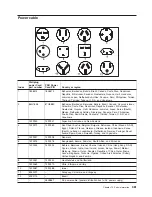
Reviews: