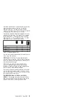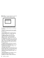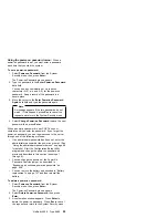
controller parameters. You also can select this choice to
run the RAID subsystems diagnostics, initialize the
controller configuration, reset the configuration values to
the factory defaults, and select a source (hard disk,
NVRAM, Flash) from which to synchronize the ServeRAID
controller configuration.
8. Exit lets you exit from the Main Menu of the ServeRAID
Configuration program.
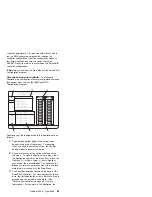
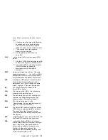
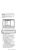
Screens and pop-up windows:
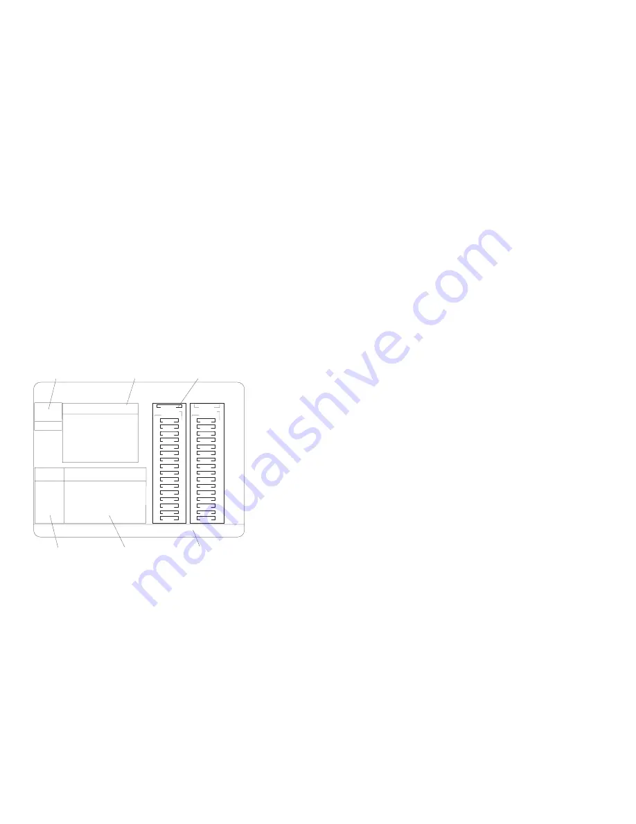
The following
illustration is a compilation of several configuration screens
that appear when you use the IBM ServeRAID
Configuration program.
Bay
Array
Bay
Array
1
2
3
4
5
6
7
8
9
10
11
12
13
14
15
16
Ch
1
Ch
2
INI
ONL
CDR
B
B
B
HSP
ONL
ONL
1
2
3
4
5
6
7
8
9
10
11
12
13
14
15
16
INI
1. Help
2. Delete Disk Array
3. Create Disk Array
4. Define Logical Drive
5. Copy Logical Drive
6. Define/Undefine Hot-spare Drive
7. Delete Logical Drive
Enter a value greater than 2 and less than the default value shown or 32X1024
whichever is lesser, and press Enter. ESC to quit.
Create/Delete/Copy Log Drive
Enter Size
of Logical
Drive,(MB)
:
3840
IBM ServeRAID Adapter Disk Array Configuration Ver. X.XX
Adapter Number: 1
Bus Number: 0 Host ID = Null Config
1
2
3
6
5
4
A
A
ONL
ONL
A
ONL
Array
ID Size(MB)
Log
Drv
Size
(MB)
RAID
Level
Status
Wrt
Pol
A0
A1
A2
B0
B1
1500
1500
1005
1500
3510
RAID-5
RAID-0
RAID-1
RAID-5
RAID-0
OKY
OKY
OKY
OKY
OKY
WT
WT
WT
WT
WT
A
B
5760
5760
Descriptions of the labeled areas in this illustration are as
follows:
1
Pop-up windows that apply to the current menu
appear in this area of the screen. For example,
when you need to confirm an action, the Confirm
pop-up window appears in this area.
2
You can select any of the choices that appear on
the menu. To make a selection from a menu, type
the highlighted number of the menu item, or use the
Up Arrow (
↑
) or Down Arrow (
↓
) key to highlight
your choice; then, press Enter. You can press the
Esc key to return to a previous menu, to a previous
work area of a screen, or to the Main Menu.
3
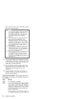
The Array/Bay selection list shows the bays for the
ServeRAID controller. For each bay that contains a
drive, the list indicates the array in which the drive is
grouped and the physical device state. (See
“Physical device states” on page 86 for more
information.) For example, in the illustration, the
Netfinity 5500 - Type 8660
85
Summary of Contents for 86604RU - Netfinity 5500 - 4RU
Page 2: ......
Page 8: ...vi Netfinity Server HMM...
Page 214: ...1 Hard disk drive 2 Drive tray handle open position 206 Netfinity Server HMM...
Page 244: ...Screws 236 Netfinity Server HMM...
Page 247: ...Netfinity 5500 Type 8660 239...
Page 314: ...306 Netfinity Server HMM...
Page 324: ...316 Netfinity Server HMM...
Page 325: ...Related service information 317...
Page 326: ...318 Netfinity Server HMM...
Page 327: ...Related service information 319...
Page 340: ...332 Netfinity Server HMM...
Page 341: ...Related service information 333...
Page 346: ...338 Netfinity Server HMM...
Page 402: ...IBM Part Number 00N5902 Printed in U S A S1 L 98 3...

