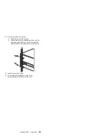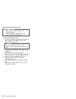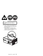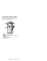
System board component locations
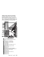
The following illustration shows the system board and
identifies system board components. You might need to
refer to this figure before you install hardware in the
server, or when you record information in the tables in this
chapter. You might also need to refer to this figure when
you set configuration jumpers on the system board.
33
34
37
32
35
38
31
36
39
40
41
42
43
44
46
45
.1/
Processor board connector (J19)
.2/
System management processor error LED
(CR24)
.3/
RAID channel 1 connector (J7)
.4/
RAID channel 1 error LED (CR30)
.5/
RAID channel 2 error LED (CR31)
.6/
Reserved (J54)
.7/
Reserved (J64)
.8/
Disable RAID controller jumper block (J11)
.9/
Reserved (J45)
.1ð/
Power on control jumper block (J32)
.11/
Reserved (J25)
.12/
Reserved (J9)
.13/
Power backplane cable connector (J8)
.14/
RAID channel 2 connector (to backplane) (J3)
.15/
RAID system error LED (CR32)
.16/
Reserved (J27)
.17/
Reserved (J35)
.18/
SCSI activity LED connector (J52)
.19/
Reserved (J34)
.2ð/
Reserved (J29)
.21/
Reserved (J26)
Netfinity 5500 - Type 8660
255
Summary of Contents for 86604RU - Netfinity 5500 - 4RU
Page 2: ......
Page 8: ...vi Netfinity Server HMM...
Page 214: ...1 Hard disk drive 2 Drive tray handle open position 206 Netfinity Server HMM...
Page 244: ...Screws 236 Netfinity Server HMM...
Page 247: ...Netfinity 5500 Type 8660 239...
Page 314: ...306 Netfinity Server HMM...
Page 324: ...316 Netfinity Server HMM...
Page 325: ...Related service information 317...
Page 326: ...318 Netfinity Server HMM...
Page 327: ...Related service information 319...
Page 340: ...332 Netfinity Server HMM...
Page 341: ...Related service information 333...
Page 346: ...338 Netfinity Server HMM...
Page 402: ...IBM Part Number 00N5902 Printed in U S A S1 L 98 3...

