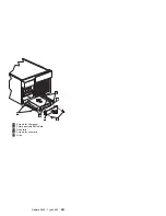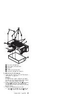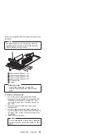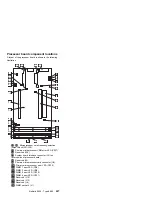
Refer to this illustration while you perform the steps in this
procedure.
Note
The illustration shows only the processor board for
simplicity; you do not need to remove the processor
board to install a memory module.
.1/
Memory socket (Bank) 1 (J4)
.2/
Memory socket (Bank) 2 (J3)
.3/
Memory socket (Bank) 3 (J2)
.4/
Memory socket (Bank) 4 (J1)
.5/
Retaining clips
.6/
DIMM
Before you begin:
Read “Safety information” on page 308.
Read the documentation that comes with the
option.
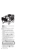
To install a memory module:
1. Turn off the server and peripheral devices and
disconnect all external cables and power cords (see
“Preparing to install options” on page 220); then
remove the top cover (see “Top cover removal” on
page 262).
2. Locate the memory-module connectors on the
memory board.
3. Touch the static-protective package containing the
memory-module kit to any unpainted metal surface on
the server. Then, remove the memory module from
the package.
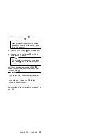
4. Install the memory module:
Note
To avoid breaking the retaining clips or damaging
the memory-module connectors, handle the clips
gently.
Netfinity 5500 - Type 8660
215
Summary of Contents for 86604RU - Netfinity 5500 - 4RU
Page 2: ......
Page 8: ...vi Netfinity Server HMM...
Page 214: ...1 Hard disk drive 2 Drive tray handle open position 206 Netfinity Server HMM...
Page 244: ...Screws 236 Netfinity Server HMM...
Page 247: ...Netfinity 5500 Type 8660 239...
Page 314: ...306 Netfinity Server HMM...
Page 324: ...316 Netfinity Server HMM...
Page 325: ...Related service information 317...
Page 326: ...318 Netfinity Server HMM...
Page 327: ...Related service information 319...
Page 340: ...332 Netfinity Server HMM...
Page 341: ...Related service information 333...
Page 346: ...338 Netfinity Server HMM...
Page 402: ...IBM Part Number 00N5902 Printed in U S A S1 L 98 3...

