


Service Processor Checkpoints
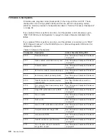
Service processor checkpoints are in the range E010 to E0FF. The message OK
indicates successful service processor testing and initialization. Firmware checkpoints
are listed in “Firmware Checkpoints” on page 88.
If you replace FRUs or perform an action, and the problem is still unresolved, go to
“MAP 1540: Minimum Configuration” on page 59 unless otherwise indicated in the
tables.
If you replace FRUs or perform an action, and the problem is corrected, go to
″
MAP
0410: Repair Checkout
″
in the
RS/6000
Eserver
pSeries Diagnostic Information for
Multiple Bus Systems.
Table 1. Service Processor Checkpoints.
Checkpoint
Description
Action/ Possible Failing FRU
DIAG STBY
Service processor is ready. The system
unit was shut down in service mode by
the operating system; however, the
system unit is still powered on.
The service processor is ready. The
operating system has been terminated;
the system is still powered on. This
usually indicates an operating system
crash. The service processor menus are
available. Look for error codes related
to the operating system crash in the
service processor error log.
E000
System support controller begins
operation. This is an informational
checkpoint.
Call support.
E010
Starting service processor self-tests
Replace the system board.
Location: P1
(See note 3 on page 109.)
E011
Service processor self-tests completed
successfully
Call support.
E012
Begin to set up service processor helps
Replace the system board.
Location: P1
(See note 3 on page 109.)
E020
Configuring CMOS
Replace the system board.
Location: P1
(See note 3 on page 109.)
E021
Configuring NVRAM
1. Manually drain the NVRAM by
removing the battery. Short circuit
the battery leads for at least 30
seconds. Use a conductive object
such as a coin or a screwdriver for
this purpose.
2. Replace the system board.
Location: P1
(See note 3 on page 109.)
E022
Accessing system board VPD
Replace the system board.
Location: P1
(See note 3 on page 109.)
82
Service Guide
Summary of Contents for 265
Page 1: ...IntelliStation POWER 9112 Model 265 Service Guide SA38 0609 00 IBM...
Page 2: ......
Page 3: ...IntelliStation POWER 9112 Model 265 Service Guide SA38 0609 00 IBM...
Page 14: ...xii Service Guide...
Page 20: ...Fan Locations 1 2 3 4 1 Fan 1 2 Fan 2 3 Fan 3 4 Fan 4 4 Service Guide...
Page 46: ...30 Service Guide...
Page 96: ...80 Service Guide...
Page 190: ...174 Service Guide...
Page 287: ...Replacement Replace in reverse order Chapter 9 Removal and Replacement Procedures 271...
Page 308: ...292 Service Guide...
Page 324: ...308 Service Guide...
Page 328: ...312 Service Guide...
Page 354: ...338 Service Guide...
Page 363: ......
Page 364: ...IBM Printed in U S A February 2002 SA38 0609 00...
Page 365: ...Spine information IBM IntelliStation POWER 9112 Model 265 Service Guide SA38 0609 00...


