background image

Operator's Manual 

43

Instrument Setup

continued

3. Instrument Settings

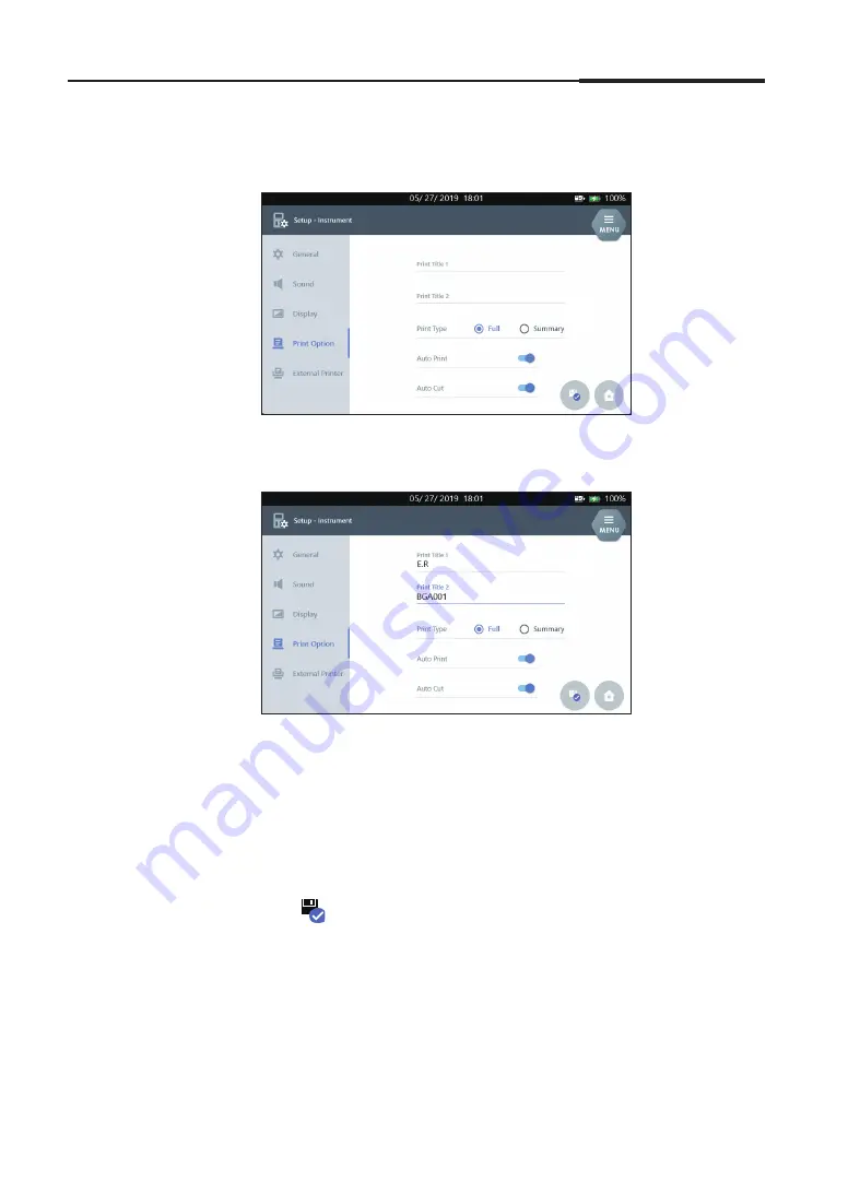
Print Option

1. Select 

Print Option

 tab.

2. Click the 

Print Title 1

 and 

Print Title 2

 text fields to enter titles of the 

thermal-printout.

3. Select 

Full

 or 

Summary

 for the 

Print Type

.

Note:


Selecting 

Summary

 will result in printing data based on the info.

4. Select 

Auto Print

 option for the automatic printout.

5. Select 

Auto Cut

 option for the automatic paper cut.

6. Press 

 to save the settings and to exit to the main screen.

Summary of Contents for i-SmartCare 10

Page 1: ...PZA1O7619 REV7 2020 12 Operator s Manual Operator s Manual...

Page 2: ...1 0 5 0 PZA1O7619 REV7 2020 12 i SENS Inc 27 36 Gwangun ro Nowon gu Seoul 01891 Korea MedicalTechnology Promedt Consulting GmbH Altenhofstrasse 80 66386 St Ingbert Germany Copyright 2020 i SENS Inc Al...

Page 3: ......

Page 4: ...Please take time to read this operator s manual before setting up and operating the analyzer...

Page 5: ......

Page 6: ...Blood Sample 69 QC Sample 78 Installation Requirements 16 Power Cable Connection 17 Power on 18 Printer Paper Installation 20 Cartridge Installation 22 Sample Data 86 QC Data 90 Calibration Data 96 Ca...

Page 7: ...ions 124 Instrument Specifications 126 Cartridge Specifications 127 Principles 128 Calibration 104 Cartridge Removal 106 Cartridge Information 109 System Information 110 Event Log 111 Analyzer Status...

Page 8: ...1 Introduction 1 Introduction Safety 8 Symbols and Terminology 10 Product Description 13...

Page 9: ...source Direct exposure to the infrared light may cause retina injury Do not look directly into the light source General Caution Make sure to connect the power cord to grounded electric outlet Do not c...

Page 10: ...azard materials must be handled and or discarded in accordance with the instructions from hospitals clinical labs or testing facilities Always protect yourself with proper safety gear such as lab gown...

Page 11: ...tive in the European community Manufacturer Temperature limitation Humidity limitation Catalogue number Batch code Contains sufficient for n tests Use by Expiration Date Biological risks This marking...

Page 12: ...ntroduction Symbol Description Printer DC Power port Power off Power on This way up indicates correct upright position of the transport package Keep dry Fragile handle with care Stacking limit by numb...

Page 13: ...al Calibration 1 Point Cal 1 Point Calibration 2 Point Cal 2 Point Calibration O2 Cal O2 Calibration QC Quality control EEPROM electrically erasable programmable read only memory Warning A statement t...

Page 14: ...ematocrit Hct and metabolites Glu Lac in whole blood samples The i SmartCare 10 Blood Gas Analyzer is intended for in vitro diagnostic use and for use by healthcare professionals Analyzer Touch Screen...

Page 15: ...14 i SmartCare 10 Blood Gas Analyzer Product Description continued 1 Introduction Analyzer Accessories Power adapter Power cord Printer Paper Cartridge Cartridge Cover CarePak Cartridge...

Page 16: ...2 Installation 2 Installation Installation requirements 16 Power Cable Connection 17 Power On 18 Printer Paper Installation 20 Cartridge Installation 22...

Page 17: ...the range of 5 40 C according to IEC 61010 1 The recommended range is from 15 to 35 C for the desirable performance Operating Humidity 5 85 relative humidity Operating Altitude Below 3 000 m Note Keep...

Page 18: ...OFF position Always use a grounded electrical outlet Use the provided the power cord and power adapter only Connect to power 1 Plug the power cord into power adapter s socket 2 Connect the adapter to...

Page 19: ...pushing the switch on the back 2 The LCD screen is turned on and the analyzer will start booting 3 Once the booting is complete the main screen appears Note When the analyzer is started without a cart...

Page 20: ...er cable is properly connected If the power connected icon does not appear even after the power cable is properly connected please contact our service teams 5 Check the analyzer s time and date If the...

Page 21: ...s Analyzer Printer Paper Installation Install printer paper 1 Open the printer cover by pressing the PUSH button located on the top of the analyzer 2 Place a paper roll in the holder and align the edg...

Page 22: ...r Installation continued Install printer paper continued 2 Installation 3 Close the printer cover Note To avoid paper jams use the manufacturer s recommended or supplied paper The roll paper can be pu...

Page 23: ...x 2 Open the cartridge cover by pressing the lock button and remove the cover Note Be careful to handle the cartridge once the cover is removed Sharp edged and components are exposed 3 Press INSTALL b...

Page 24: ...artridge continued 2 Installation 5 Follow the instructions on the screen 6 Insert the cartridge into the analyzer with the label facing towards the front of the analyzer 7 When Close cartridge door m...

Page 25: ...nstall Cartridge continued 2 Installation 8 The i SmartCare 10 automatically recognizes the cartridge information once the cartridge door is closed 9 If the cartridge EEPROM information is valid the w...

Page 26: ...Cartridge Warm Up is completed the following Ready screen appears Note Any parameter not supported by the cartridge is marked with a line displayed as inactive Depending on the status of the cartridge...

Page 27: ...2 Installation 26 i SmartCare 10 Blood Gas Analyzer This page is intentionally left blank...

Page 28: ...nt Settings 3 Instrument Settings Screen Menu 28 Instrument Setup 37 Parameter Setup 46 Parameter Group Setup 48 Unit Setup 50 Sample Setup 52 QC Setup 58 L J Chart Setup 61 Interface Setup 63 Languag...

Page 29: ...idge expiration Current Date and Time Interface setup status Battery and power connect status Battery level Parameter Group widget Analyzer operation schedule widget Menu Button Start analysis button...

Page 30: ...ar when MENU is pressed 2 Press a category icon to select the associated sub categories Note MENU button is disabled on the following screens Install Cartridge Remove Cartridge Introduce Sample Sample...

Page 31: ...30 i SmartCare 10 Blood Gas Analyzer Screen Menu continued 3 Instrument Settings Menu options...

Page 32: ...ons Function View function button Print results or settings on screen Print to external printer Transmit results to LIS HIS Return to main screen Go to the list View result Scroll to previous next pag...

Page 33: ...continued 3 Instrument Settings Button icons Function Run 1 point calibration 2 point calibration O2 calibration SampleType Syringe Capillary QC Run QC sampling Run syringe sampling Run capillary sam...

Page 34: ...Menu continued Icons and buttons continued 3 Instrument Settings Button icons Function Parameter Group Analyzer operation schedule Add Delete Scan QC barcode Manually input QC Edit Restore default va...

Page 35: ...r Screen Menu continued Icons and buttons continued 3 Instrument Settings Button icons Function Deselect an item on the list Select an item on the list Scan barcode for data entry Enable the interface...

Page 36: ...ntinued 3 Instrument Settings Keyboards The i SmartCare 10 is equipped with various digital keyboards pads for easy data entry Alphabet keyboard Numbers and special characters keyboard Date entry keyp...

Page 37: ...nformation Function about to be performed in the analyzer or the current function Steps the operator needs to follow such as sample collection or cartridge replacement Error messages Voice guide The a...

Page 38: ...SETUP Instrument Date format Date Time Instrument Name Default Sample Type Barometric Pressure Speaker volume LCD brightness Print Option External Printer Note Date format and Date and Time can be se...

Page 39: ...ings 3 Select General 4 Press Date Format text field and select a desired date format from the drop down list 5 To Change the time press Date text field and enter the current date using the keypad 6 P...

Page 40: ...continued 3 Instrument Settings Instrument Name 1 Press Instrument Name text field and enter a desired name using the keyboard Note The entered instrument name will appear on all the set up printouts...

Page 41: ...1 Press Default Sample Type text field and select a desired sample type from the drop down list Note The selected sample type is applied on the main screen as the default sampling condition Ex If Syr...

Page 42: ...alue where the analyzer is located Note BP Default Value is set to 760 mmHg by default The entered value will be used as a default value on the Sample Information page and used for output calculation...

Page 43: ...Sound button clicked Drag the cursor up or down to adjust the volume of the sound LCD Brightness Setup 1 Click Display to adjust the LED Brightness Drag the cursor up or down to reach a desired brigh...

Page 44: ...t Title 2 text fields to enter titles of the thermal printout 3 Select Full or Summary for the Print Type Note Selecting Summary will result in printing data based on the info 4 Select Auto Print opti...

Page 45: ...Printer Note If the analyzer is not connected to the network Disconnected will appear 1 In order to add a printer desired to the unit Select External Printer tab and press ADD EXTERNAL PRINTER 2 The...

Page 46: ...he analyzer 5 Once the installation is finished Press Finish The Operating software will start 6 Select External Printer Tab The installed printer appears in Network Printer List 7 Select the desired...

Page 47: ...or is displayed in Measured Parameter category 2 The test parameters can be selected by checking desired boxes from Measured and Calculated Parameters shown on the Parameter Setup screen Note Activati...

Page 48: ...inued Parameter Setup continued 3 Instrument Settings Note The selected parameters from the Parameter Setup affect the followings Main screen Result screen and result print Calibration List page and p...

Page 49: ...Parameter Group 2 Press Add Parameter Group and the following categories in parameter group for selection screen will be displayed 3 Enter Group Title and select measured and calculated parameters 4 P...

Page 50: ...gs Parameter Group Setup continued 5 Once the configured group is chosen Delete and Edit buttons appear as below Note Press Edit to edit selected group Press Delete to delete selected group 6 Press to...

Page 51: ...zer Unit Setup 1 Select MENU SETUP Unit 2 Units of parameters Measured Value Calculated Value and User input values can be selected from the drop down lists 3 Press for further options Press button to...

Page 52: ...ction L L Glu mg dL mmol L Lac mmol L mg dL mEq L Temperatures FIO2 fraction tHb g dL g L mmol L sO2 fraction pO2 A a mmHg kPa tCO2 mmol L Vol mL dL HCO3 mmol L mEq L HCO3 std mmol L mEq L BE B mmol L...

Page 53: ...eference Ranges Setup 2 Once the configuration units are selected from the list of units the following screen with range enter will be displayed Note The unit selected from Setup Unit is used 3 Using...

Page 54: ...entered value is invalid Prior to saving the value please check if the entered values meet the following criteria Both low and high values are entered The low value must be smaller than the high valu...

Page 55: ...Select MENU SAMPLE Critical Limits Setup 2 Once the configuration units are selected from the list of units the following screen with range enter will be displayed Note The unit selected from Setup U...

Page 56: ...red values meet the following criteria Both low and high values are entered The low value must be smaller than the high value The high value must be set higher than the high value of the reference ran...

Page 57: ...ontinued 3 Instrument Settings Correlation Factors Setup 1 Select MENU SAMPLE Correlation Factors Setup 2 Turn the Correlation Factors Apply on the window with default values becomes active 3 Check ea...

Page 58: ...Offset range pH 0 00 9 99 99 9999 pCO2 0 00 9 99 99 99 pO2 0 00 9 99 99 9 Na 0 00 9 99 99 9 K 0 00 9 99 99 99 Ca2 0 00 9 99 99 999 Cl 0 00 9 99 99 9 Hct 0 00 9 99 99 9 Glu 0 00 9 99 99 9 Lac 0 00 9 99...

Page 59: ...Analyzer QC Lot Setup 1 Select MENU QC Setup 2 Once selected in the Add QC list Barcode and Manual buttons are displayed as follows 3 When using the QC material with the QC barcode provided by i SENS...

Page 60: ...matically entered once the QC barcode is recognized Note When the unit is changed from Setup Unit and the QC Information is manually entered the QC Range Values are saved automatically in the unit cha...

Page 61: ...t be entered in the changed value 6 Press OK to save the setting and to go back to the QC Setup screen 7 When entered units are selected Delete and View buttons are displayed Note Press Delete to dele...

Page 62: ...ttings Operator s Manual 61 L J Chart Setup L J Chart Setup 1 Select MENU QC L J Chart Setup 2 Select QC level on the top of the screen 3 To set up the SD range select the SD range in each unit s SD s...

Page 63: ...L J Chart Setup continued 3 Instrument Settings 4 To manually set up the lower and upper limit select Lower Limit and Upper Limit located on the right 5 Using the numeric keypad enter low and high lim...

Page 64: ...before starting the interface set up 1 Select MENU SETUP Interface Send Option 1 Select Send Option tab 2 Select the data type to send by checking the box next to the data type Sample QC Cal 3 Select...

Page 65: ...ect the desired option from the drop down list Default is set at 8 4 Press Stop Bit text field and select the desired option from the drop down list Default is set at ONE 5 Press Parity Bit text field...

Page 66: ...pears in each item of IP and DNS in the TCP IP Setup tab 2 To manually set up the IP and DNS information select the Manual IP and Manual DNS 3 Press IP entry text field and enter necessary information...

Page 67: ...Language text field and select a desired language from the drop down list 3 Press to save the settings and to exit to the main screen Note Currently i SmartCare 10 offers English Spanish German Italia...

Page 68: ...4 Sample Analysis 4 Sample Analysis Start Analysis 68 Blood Sample 69 QC Sample 78...

Page 69: ...ple analysis starts from the main screen 1 Check if START button is in active status on the main screen as shown below 2 Select the sample type Note Supported sample types are as below Icon Sampling m...

Page 70: ...ry mode Note The sampler will be automatically in position according to its selected mode To cancel the sample analysis press X located on the lower right before aspiration occurs 2 Place the Syringe...

Page 71: ...ating sample Please wait message appears as the sample is aspirated into the analyzer 5 When the sample aspiration is complete the message Remove sample now appears Please remove the sample container...

Page 72: ...on 1 If the sample aspiration process is done correctly Sample Information screen is displayed with the selected sample type on the top of the screen Note Items with units appear with the units select...

Page 73: ...s 3 Scan the barcode to enter sample information using the barcode scanner located in the front of the analyzer Note The sample information may be entered manually by using the keyboard 4 Once the inf...

Page 74: ...le Results Screen Printouts and Interface messages will display the units selected from Setup Unit 1 When the sample analysis is complete the result appears under the Measured tab in the Sample Result...

Page 75: ...t is lower than the Critical Limit 6 When the sample result is out of the measuring range no result is shown And Reportable Range Error message appears 7 The result with the Slope Error does not produ...

Page 76: ...ditional information Tab Note Sample information is displayed only for the samples that had been selected in the Sample Information screen 10 The analyzer goes through Rinse and 1 Point Cal process be...

Page 77: ...e performed Press button to send the result to LIS HIS Press button to print out the results There are the examples of printout Note When the analyzer is running on a battery and the battery level is...

Page 78: ...Blood Sample continued Sample Results continued 4 Sample Analysis If Summary is selected in the Print Type option only entered sample information will be printed 12 Press to save the results and to ex...

Page 79: ...pling does not affect the remaining test counts 1 Check if START button is in active status on the main screen as shown below Note Once the QC is selected START button color will be changed to purple...

Page 80: ...ait until the sampler probe has fully reached to its aspiration position Note To cancel the QC sample analysis press X on the lower right hand corner before aspiration occurs 3 When the sampler probe...

Page 81: ...C sample from the sampler probe at once 6 Please wait until the sampler is automatically closed Once the aspiration is successfully finished the screen will change to QC Information Note If the QC sam...

Page 82: ...nt QC sampling Note QC Lot which was configurated by the user in the QC Setup will appear If required enter the Operator ID using the barcode or the on screen keyboard If required enter the QC Comment...

Page 83: ...es display their results in the units selected from Setup Unit 1 When QC sample analysis is complete the following screen appears Note If the result is higher than the QC range appears next to the res...

Page 84: ...on the QC results press either Accept or Discard button The result status on the upper right hand corner changes from PENDING to ACCEPTED or DISCARDED Note Select PENDING if acceptance is not certain...

Page 85: ...the result to LIS HIS Press button to print out the results There are the examples of printout Full Summary Note If Summary is selected in the Print Option only entered QC information will be printed...

Page 86: ...5 Database 5 Database Sample Data 86 QC Data 90 Calibration Data 96 Cartridge Data 97...

Page 87: ...following functions can be performed Press or to see the previous or next results Press button to print out the results Press to go to the list of Sample Results Press button to send results to LIS H...

Page 88: ...descending order the latest result on top 2 Press and the following functions can be performed Use or to scroll the results To search the results click button The sample result search screen appears T...

Page 89: ...10 parameters can be viewed thought the smart view window Note For further detailed results press the button located at the end When the Insufficient sample error occurs sample result is not shown in...

Page 90: ...arch date range Sample Type Patient ID Sample ID Patient Last Name Patient First Name Operator ID 2 Enter the desired search criteria into the search text field or use the drop down list 3 Press and t...

Page 91: ...ng results will be confirmed by Accept and Discard button 2 Press and the following functions can be performed Press or to see the previous or next results Press button to print out the results Press...

Page 92: ...order the latest result on top 2 Press and the following functions can be performed Use or to scroll the results To search the results click button The sample result search screen appears To send the...

Page 93: ...meters can be viewed thought the smart view window Note For further detailed results press the button located at the end When the Insufficient QC sample error occurs QC sample result is not shown in t...

Page 94: ...te of the search date range QC Lot Accepted Discarded Pending QC or other results Operator ID 2 Click a search text field or dropdown menu and enter desired search criteria 3 Press and the searched QC...

Page 95: ...QC results per a QC Lot 5 Press and the following functions can be performed Press button to print out the QC statistics Press and the QC statistics data will be printed through the configured externa...

Page 96: ...igured SD value from the QC L J Chart Setup is indicated with shaded lines and the data which are out of SD range are marked as red dot 3 Press and the following functions can be performed Press and t...

Page 97: ...meters that had been selected in the Setup Parameter 2 Press and the following functions can be performed Use or to scroll the list Press the button to print the selected data Press the button to send...

Page 98: ...ata 1 Select MENU CARTRIDGE Data Note The Cartridge Data list appears in descending order the most recent result on top 2 Press and the following functions can be performed Use or to the cartridge dat...

Page 99: ...Cartridge Data Copy 1 Insert USB memory into one of the analyzer s USB ports 2 Data copy in progress Please wait message appears 3 Once the data copy is complete Cartridge data copy completed Remove U...

Page 100: ...6 Shutdown 6 Shutdown Analyzer Shutdown 100 Power Recovery 102...

Page 101: ...t down steps may result in data loss or damage in components The cartridge cannot be removed while the power is turned off or during the shutdown process Shutdown Analyzer 1 Select MENU MAINTENANCE Sh...

Page 102: ...Shutdown 3 Press YES and the following screen appears 4 Turn off the analyzer message appears Then turn off the power by pressing the mark Note To remove the power cable from the analyzer unplug the p...

Page 103: ...rs The analyzer is analyzing a sample when the power was interrupted and the power is restored within 20 minutes The analyzer was measuring the QC when the power was out and the power was restored wit...

Page 104: ...7 Maintenance 7 Maintenance Calibration 104 Cartridge Removal 106 Cartridge Information 109 System Information 110 Event Log 111 Analyzer Status 112 Cleaning 114...

Page 105: ...sending only appears on calibration list page 1 Select MENU CALIBRATION Run 1P Cal to perform 1 Point Cal 2 Select MENU CALIBRATION Run 2P Cal to perform 2 Point Cal Note When the slope error appears...

Page 106: ...bration performed appears as blue normal or red Slope Error Note Parameters that are not selected in the Setup Parameter are marked in grey Parameters that are not supported by the inserted cartridge...

Page 107: ...rzard meterial If the analyzer is not used and is being stored in storage for a long time take out the cartridge and turn off the power Expired Cartridge 1 When a cartridge is expired for any of the f...

Page 108: ...red Cartridge screen and the following screen appears 3 Start the cartridge removal procedure following the instructions on the screen Note Do not put the cartridge cover back on the removed The cartr...

Page 109: ...en if the expiration date and the number of tests are still valid When the analyzer is running on a battery and the battery level is below 40 the cartridge replace is not available 2 Press YES and the...

Page 110: ...lot number installation date time expiration date time cartridge age Calibration information concentration of Cal 1 Cal 2 and Cal3 solutions Note Any unsupported parameters of the cartridge are not i...

Page 111: ...Analyzer System Information System Information 1 Select MENU MAINTENANCE System Information 2 System Information screen includes the followings Software version Firmware version Instrument name Serial...

Page 112: ...Interface transmission related errors Operating software related events DB errors Calibration related events Calibration Error Auto Cal Saving procedure errors Cartridge installation and replacement...

Page 113: ...od Gas Analyzer Analyzer Status Analyzer Status 1 Select MENU MAINTENANCE Analyzer Status 2 Raw Signal tab includes the following information Sensors raw signals Note Any unsupported parameters in the...

Page 114: ...d Note When the cartridge is correctly installed the Cartridge status will be indicated as Installed The Cartridge Door Sampler and Sampler door status will be indicated as Closed Temperature unit wil...

Page 115: ...t apply too much force when wiping the analyzer s screen Dispose any biohazard materials after cleaning in accordance with the lab s guidelines and procedure Cleaning procedure 1 Use 0 5 sodium hypoch...

Page 116: ...8 Troubleshooting 8 Troubleshooting Troubleshooting 116 Error Code 122...

Page 117: ...l do not see the red light insert a sharp object e g a paperclip or a mechanical pencil tip into the SCAN hole next to the DISK LED on the back of the analyzer and press once 3 The scanner may not aut...

Page 118: ...rn the power switch on 5 The analyzer should be turned on and the battery starts charging 6 If the analyzer is not on turn off the power switch again 7 Charge the battery for approximately 10 minutes...

Page 119: ...still does not work try a different USB memory Cartridge data copy has failed message appears while the data copy is in progress 1 Close the message popup window and try again from the beginning 2 Sel...

Page 120: ...n In case you experience one of the following issues The analyzer is turned off The analyzer is not turning on 1 If the analyzer s power switch is on turn it off 2 Check if the connection between the...

Page 121: ...Check if the connection between the analyzer and the power outlet is loose 2 Open the printer cover 3 If the printer is out of paper load paper 4 If the paper is jammed remove the jammed paper and pr...

Page 122: ...e measurement range A result is suspicious 1 Try sample analysis again with the same sample 2 If the same error occurs run 2 Point Cal 3 Try the sample analysis again 4 Repeat 2 Point Cal a few times...

Page 123: ...peration of the analyzer Error Code Description ESYS001 ESYS999 Hardware errors EDB001 EDB999 Database errors ESW001 ESW999 Software errors 2 Take note of the error code 3 Turn off the analyzer 4 Wait...

Page 124: ...9 Product Specifications 9 Product Specifications Operation Specifications 124 Instrument Specifications 126 Cartridge Specifications 127 Principles 128...

Page 125: ...e 100 L Sample introduction method Aspiration Sample analysis time 50 seconds Sample analysis temperature 37 0 0 2 C Measuring principle electrochemical potentiometry amperometry conductometry Calibra...

Page 126: ...ers and Ranges Parameter Description Unit Input range pH T Temperature corrected pH 6 000 8 500 pCO2 T Temperature corrected pCO2 mmHg 0 0 250 0 HCO3 Bicarbonate mmol L 0 0 99 0 HCO3 std Standard bica...

Page 127: ...232 LAN RJ45 Ethernet HDMI Power adapter Input 100 240 Va c 1 5 A 50 60 Hz Max 1 5 A Output 24 Vd c Max 2 7 A Input power 24 Vd c Max 2 7 A Internal battery 14 52 V 5200 mAh Lithium ion cell 4S2P Dis...

Page 128: ...dering information Shelf life 6 months from the manufacturing date unopened Storage temperaure 15 25 C unopened Components Sensor card Sampler Waste bag Valve and tubing Solution bag Cal 1 solution ap...

Page 129: ...ical Potentiometry ion selective electrode Amperometry Conductometry pH pCO2 Na K Ca2 Cl pO2 Glu Lac Hct Once a cartridge is installed into the analyzer the instrument will perform scheduled 1 point C...

Page 130: ...use a blood collection container syringes capillaries capillary tubes etc processed with heparin Using a container with spray dried heparin or solid heparin is recommended Blood collection container...

Page 131: ...ests 2 weeks 1082050 1 100 Tests 2 weeks 1082100 1 200 Tests 2 weeks 1082200 1 300 Tests 2 weeks 1082300 1 50 Tests 3 weeks 1083050 1 100 Tests 3 weeks 1083100 1 200 Tests 3 weeks 1083200 1 300 Tests...

Page 132: ...Operator s Manual 131 Appendix B Order Information 3 Analyzer Accessories Product Description Part No Order Unit Power adapter 3152 1 Power cord 3153 1 Printer paper 3331 1 pack 4 rolls...

Page 133: ...d by external force or drop Any malfunction caused by using unapproved consumables or parts The failure caused by not following the cautions listed in the operator s manual or failing to observe the c...

Reviews: