FusionModule1000A40 ICT Solution
Maintenance Guide
4 Parts Replacement
Issue 01 (2019-03-05)
Copyright © Huawei Technologies Co., Ltd.
151
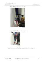
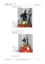
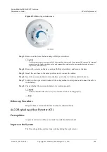
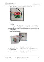
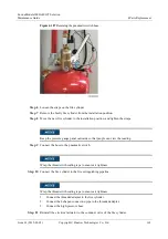
Figure 4-96
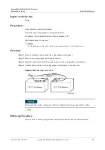
Removing screws
Step 3
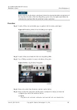
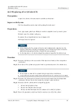
Remove the cables from the warning signs, and label the cables.
Step 4
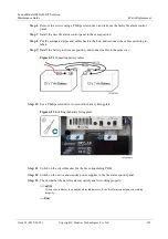
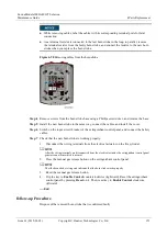
Remove the screws on the base using a Phillips screwdriver, and remove the base.
Step 5
Install the new warning sign base in the same way, and connect the cables.
Step 6
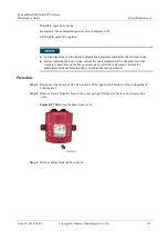
Install the warning sign cover.
Step 7
Switch on the input circuit breaker of the extinguishant control panel, and connect the battery
cables.
Step 8
Check whether the new warning sign indicator is working properly.
1.
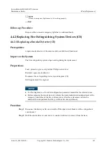
Pull up the reset button on the pneumatic switch to short-circuit the cables within to
simulate a warning sign.
If the warning sign turns on, the warning sign is working properly.
2.
Press the reset button on the pneumatic switch.
3.
Flip the key to
Enable Control
counterclockwise (rightward). Reset the extinguishant
control panel by pressing
Reset
on it. Then, reset key to
Enable Control
clockwise
(leftward).
----End
Follow-up Procedure
Dispose of the removed warning sign indicator that is confirmed faulty.
4.4.2.4 Replacing an Internal Horn Strobe (CE)
Prerequisites
A spare horn strobe of the same model is available and functional.
Impact on the System
The fire extinguishing system stops working during the replacement.
Preparations
Tools: Phillips screwdriver, step ladder

