FusionModule1000A40 ICT Solution
Maintenance Guide
4 Parts Replacement
Issue 01 (2019-03-05)
Copyright © Huawei Technologies Co., Ltd.
125
For the diagrams, see the initial configuration parameter manual for the solution in use.
Before replacing the gas release indicator, inform the related administrative departments of
the temporary downtime of the fire extinguishing system. After the replacement, inform
the administration department that the system has become operational.
Procedure
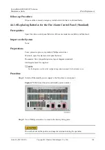
Step 1
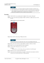
Switch off the active and standby power supplies to the fire alarm control panel.
Step 2
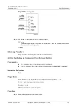
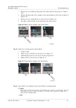
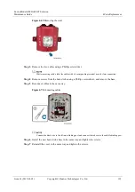
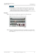
Remove the screws shown in Figure 4-66 using a Phillips screwdriver, and remove the panel.
Figure 4-66
Removing the screws
Step 3
Remove the cables using a flat-head screwdriver and label the cables.
Step 4
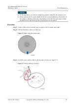
Remove the screws on the base using a Phillips screwdriver, and remove the base.
Step 5
Install the new base in the same position.
Step 6
Reconnect cables in the same way.
Step 7
Secure the panel to the base.
Step 8
Switch on the active and standby power supplies to the fire alarm control panel.
Step 9
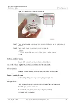
Check whether the new gas release indicator is working properly.
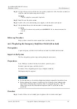
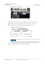
1.
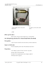
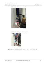
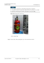
Disconnect the red and black cables from the pressure announciator, as shown by (1) in
Figure 4-67.
2.
Short-circuit the cables from the fire alarm control panel to the pressure announciator, as
shown by (2) in Figure 4-67.
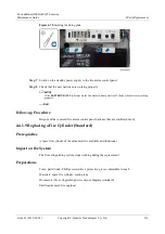
If the gas release indicator turns on, the gas release indicator is working properly.


