Automatic time markers options
When you select the T Markers field, a pop-up menu appears. When you
choose the Auto field in the pop-up a pop-up menu for automatic time
marker measurements is displayed.
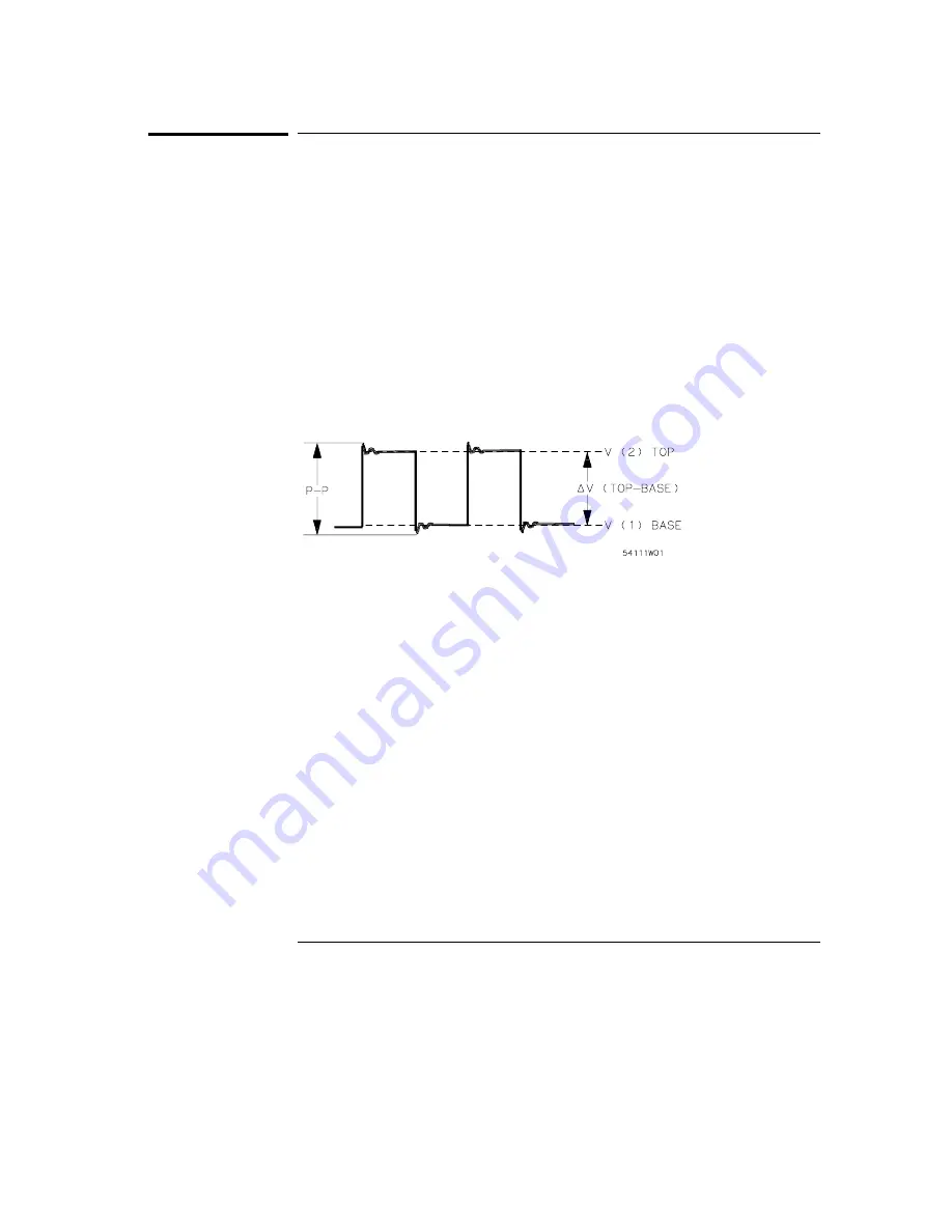
The automatic time marker measurements are made by setting the time
markers to levels that are a percentage of the top-to-base voltage value of a
waveform or to specific voltage levels. The top-to-base voltage value of a
wavform is typically not the same as the peak-to-peak voltage value. The
oscilloscope determines the top and base voltages by finding the flattest
portions of the top and bottom of the waveform. The top and base values do
not typically include preshoot or overshoot of the waveform. The
peak-to-peak voltage is the difference between the minimum and maximum
voltages found on the waveform.
If the signal is clipped, the time markers will not be automatically placed.
When searching for the marker patterns, the search will occur only on that
part of the waveform that is displayed, not the entire stored waveform.
The default Auto markers pop-up menu options are discussed in the
following sections.
Set on field
The Set on field assigns an input waveform to the Tx or To marker, or allows
the marker to be set manually (with the MANUAL selection in the pop-up).
When you select the Set on field, a pop-up appears showing the waveform
sources available.
The default selection for the Set on field is the lowest letter and number
combination.
The Scope Marker Menu
Automatic time markers options
7-90
Summary of Contents for 1660CS
Page 5: ...Introduction iv ...
Page 16: ...1 Logic Analyzer Overview ...
Page 24: ...2 Connecting Peripherals ...
Page 33: ...2 10 ...
Page 34: ...3 Using the Logic Analyzer ...
Page 55: ...3 22 ...
Page 56: ...4 Using the Trigger Menu ...
Page 75: ...4 20 ...
Page 76: ...5 Triggering Examples ...
Page 109: ...5 34 ...
Page 110: ...6 File Management ...
Page 119: ...6 10 ...
Page 120: ...7 Reference ...
Page 221: ...7 102 ...
Page 222: ...8 System Performance Analysis SPA Software ...
Page 241: ...SPA Time Interval System Performance Analysis SPA Software SPA measurement processes 8 20 ...
Page 252: ...9 Concepts ...
Page 284: ...10 Troubleshooting ...
Page 298: ...11 Specifications ...
Page 311: ...11 14 ...
Page 312: ...12 Operator s Service ...
Page 324: ...Troubleshooting Flowchart 2 Troubleshooting To use the flowcharts 12 13 ...
Page 337: ...Glossary 4 ...


